5 / 12
Siemens
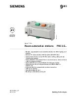
PXC3.E... Room automation stations
CM1N9203en_05
Building Technologies
2015-11-23
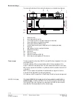
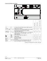
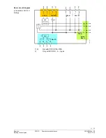
The internal bus supplies can be reinforced by external power supply modules.
An additional TXS1.12F10 supply module must be switched on and off at the same
time as the room automation station. Otherwise, DC 24 V island bus supply may
sag, resulting in alarms.
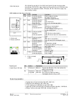
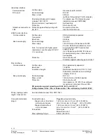
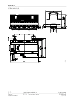
LED indicators
(depending on the type)
920
3z
02
RUN
FLT
IB
PL
DALI
SRV
1)
2)
1) Service pin
2) Service pin DALI
927
0Z
05
8 7 6 5 4 3 2 1
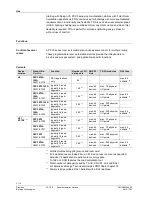
LED
Color
Activity
Function
RUN Green Continuously ON
Continuously OFF
Flashing
Device ready to operate.
No supply for device.
Start-up or program halted
FLT
Red
Continuously OFF
Continuously ON
Rapid flashing
OK
HW or SW error.
Wrong or corrupted application.
IB
Yellow Continuously ON
Flashing
Continuously OFF
OK.
Island bus communication.
No modules connected
TX-I/O modules not configured or
communication fault.
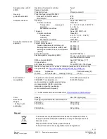
PL
Yellow Continuously ON
Flashing
Continuously OFF
OK.
KNX PL-Link communication.
KNX PL-Link not used or communication
fault.
DALI Yellow Continuously ON
Flashing
Continuously OFF
OK
DALI bus communication
DALI not used or communication fault.
SVC Red
Continuously OFF
Blinking
Blinking per wink
command*)
OK.
No application loaded.
Physical identification of the room
automation station.
Ether-
net
1 / 2
Green Continuously ON
Continuously OFF
Flashing
Link active
Link inactive
Network activity
Yellow Continuously ON
Continuously OFF
Link 100 Mbps
Link 10 Mbps
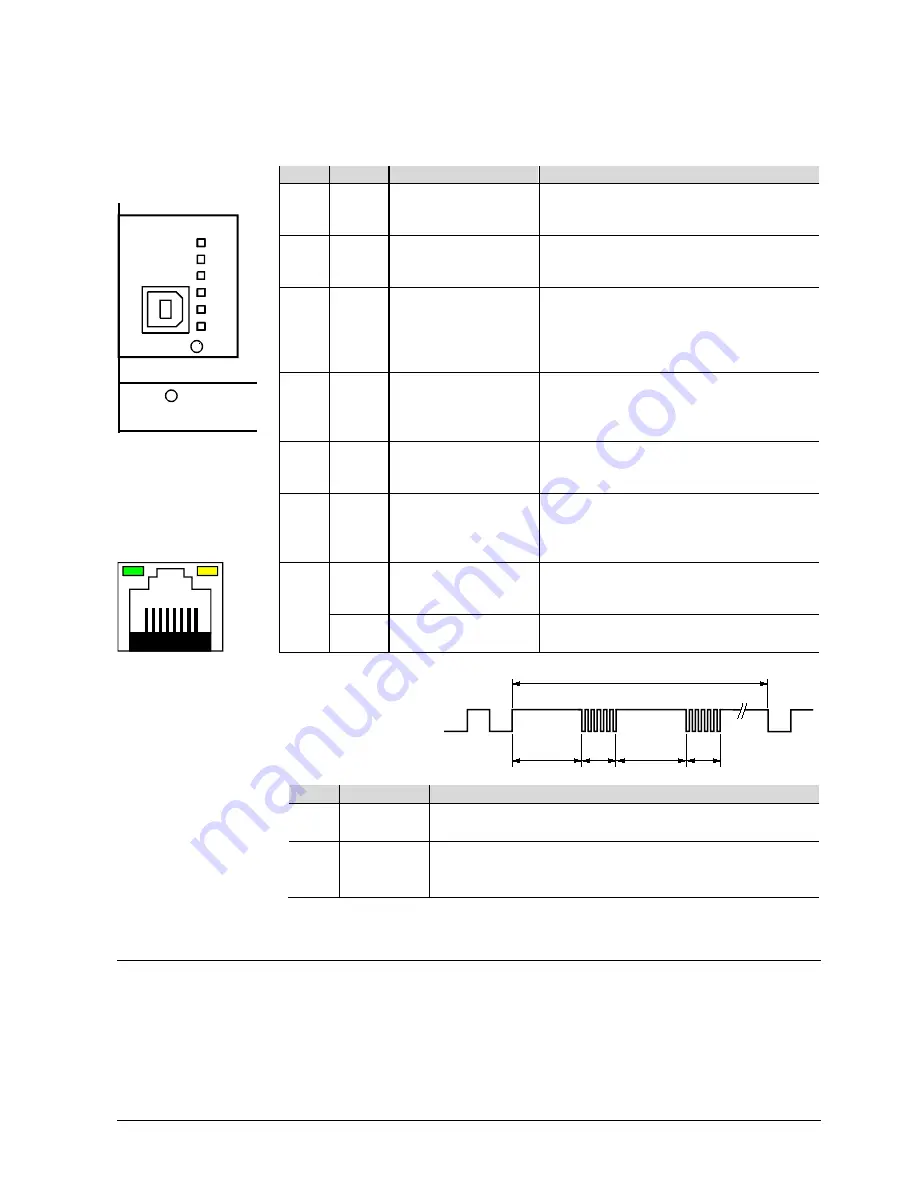
*) Wink command
pattern:
2s
1s
21s
5 Hz
5 Hz
9222z02
2s
1s
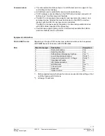
Service pins
Pin
Action
Description
(depending on the type)
1)
Short press Ethernet Physical identification of the room automation
station in the network.
2)
Short press DALI test: All ballasts On or Off.
Long press DALI test: Start / stop the following function:
"All ballasts blink (2 s On, 2 s Off)".
Product documentation
•
Engineering and commissioning: See ABT online help.
•
Installation manual Desigo TRA, CM111043.
•
TX-I/O planning and installation manual, CM110562.
•
Application Guide for IP Networks in Building Automation Systems, CM110668.
•
Desigo Technical principles CM110664, chapters 18 and 26.
Island bus supply