LMR-A: Manual mode
1A : Keep the LMR-A in Manual mode.
1B : Switch ON 3-Phase incoming main supply.
1C : Amber LED will start blinking for a period of min 0.5 min.
1D : 0.5 min is the default setting which can vary from min 0.5 min to max.5min.
1E : After the ON-delay duration, amber LED will ON continously indicating that the incoming supply
is Healthy (Assuming incoming supply is healthy).
1F : Press the green push putton for switching ON the starter.
1G : Starter gets switched ON.
1H : Press the red push button for switching OFF the starter.
1I : Starter gets switched OFF.
1J : Amber LED indication remains continous ON.
1K : Switch OFF the 3-phase incoming main supply.
1L : Amber LED indication gets turned OFF indicating that there is no incoming main supply.
LMR-A: Auto mode
1A : Keep the LMR-A in Auto mode.
1B : Switch ON the 3-Phase incoming main supply.
1C : Amber LED will start blinking for a period of min 0.5 min.
1D : 0.5 min is the default setting which can vary from min 0.5 min to max.5min.
1E : After the ON-delay duration, amber LED will ON continously indicating that the incoming supply is
healthy(Assuming incoming supply is healthy).
1F : Not applicable (No need to press ON push button)
1G : Starter gets switched ON automatically.
1H : Press the red push button and lock by mechanical latch for switching OFF the starter.
1I : Starter gets switched OFF.
1J : Amber LED indication remains continous ON.
1K : Switch OFF the 3-phase incoming main supply.
1L : Amber LED indication gets turned OFF indicating that there is no incoming main supply.
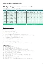
1.5: Operating procedure in normal condition
Starter operation:
LMR-A
Mode
Manual
Auto
Bypass
Amber
LED
indication
Blink
(On-delay
duration)
Blink
(On-delay
duration)
Blink
(On-delay
duration)
On-
Delay
0.5-
5min
0.5-
5min
0.5-
5min
Amber
LED
ON
ON
ON
‘ON’
Push
button
ON
ON
ON
Starter
Operation
ON
ON
ON
ON
ON
ON
‘OFF’
Push
button
OFF
Lock
OFF
Starter
Operation
OFF
OFF
OFF
Amber
LED
indication
OFF
OFF
OFF
Amber
LED
Table: 4 ADOL operating sequence in normal condition
1A
3
ф
main
supply
ON
ON
ON
1B
1C
1D
1E
1F
1G
1H
1J
1K
1L
1I
ON operation
OFF operation
Installation, Maintenance & Troubleshooting guide
| Version 01
10
3
ф
main
supply
OFF
OFF
OFF
Summary of Contents for RAJA+ 3TE7111-2BC21-1A Series
Page 1: ...Installation Maintenance Troubleshooting Guide For RAJA Agriculture Starters Controllers ...
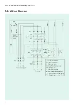
Page 5: ...1 2 Wiring Diagram Installation Maintenance Troubleshooting guide Version 01 5 ...
Page 6: ...6 Control logic diagram Installation Maintenance Troubleshooting guide Version 01 ...
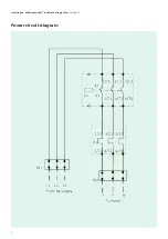
Page 7: ...7 Power circuit diagram Installation Maintenance Troubleshooting guide Version 01 ...


