1.4: Installation
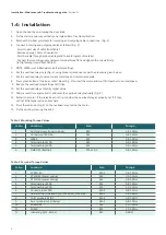
1. Open the door by unscrewing the door knob.
2. Fix the starter enclosure vertically on a rigid surface free from vibration.
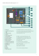
3. Remove the rubber grommets for incoming and outgoing cable connections. (Fig: 2)
4. Connect incoming and outgoing cables as follows (Fig: 2)
-Select correct size of cable from Table 1.
-Remove approx. 10mm of insulation.
-Pass the cable through proper cable gland to avoid ingress of material.
-Connect the incoming supply cables to terminal block TB1 and tighten the screws firmly
(ref.tightening torque from Table 3).
5. NOTE: LMRA is set in Manual mode (Factory setting).
6. Set the overload relay scale (Fig: 2) using proper screw driver as per the procedure given below.
7. Set the overload relay to rated current mentioned on motor name plate.
8. Press green button of the Aux.contact block (Fig: 2) to start the motor and wait till it reaches to normal speed.
9. Reduce the overload relay settings till it trips.
10. Set the overload relay at slightly higher value.
11. Allow a reset time approx 4min. and reset the overload relay manually (Fig: 2)
12. Restart the motor. If the relay does not trip, consider the overload relay as properly set. If it trips,
set it at little higher value and recheck.
13. Press the red knob (Fig: 2) on the overload relay to stop the motor
14. Fix the door by screwing the knob
9
Table: 2 Mounting Torque Values
Sr. No
Location
Size
Torque
1
Earthing screw (cover to body)
M5
2.5-3.0Nm
2
Contactor 3TS30..36
M4
0.8-1.4Nm
3
LMR-A
M4
0.8-1.4Nm
4
Terminal block 30A
M4
0.8-1.4Nm
5
Terminal block 60A
M4
0.8-1.4Nm
6
ON& OFF /Rest link
ST4.2x9.5
0.8-1.2Nm
Table: 3 Terminal Torque Values
Sr. No
Location
Size
Torque
1
3TS30..32
M3.5
0.8-1.4Nm
2
3TS33/34 (Power wiring)
M4
1.0-1.5Nm
3
3TS35/36 (Power wiring)
M5
2.5-3.0Nm
4
Terminal block 30A
M4
0.8-1.4Nm
5
Terminal block 60A
M5
1.5-2.1Nm
6
Contact block 3SB5
M3.5
0.8-1.2Nm
7
Aux terminal (side add on) of 3TS35/36, 3TS33/34
M3.5
0.8-1.4Nm
8
Coil Terminals A1/A2
M3.5
0.8-1.2Nm
9
Aux. terminals of all Relays
M3.5
0.8-1.2Nm
10 3UW51/52
M4
1.0-1.5Nm
11 3US56
M5
2.5-3.0Nm
12
Indicating light - Amber
M3
0.8Nm
Installation, Maintenance & Troubleshooting guide
| Version 01
Summary of Contents for RAJA+ 3TE7111-2BC21-1A Series
Page 1: ...Installation Maintenance Troubleshooting Guide For RAJA Agriculture Starters Controllers ...
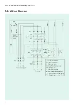
Page 5: ...1 2 Wiring Diagram Installation Maintenance Troubleshooting guide Version 01 5 ...
Page 6: ...6 Control logic diagram Installation Maintenance Troubleshooting guide Version 01 ...
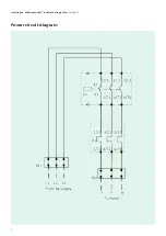
Page 7: ...7 Power circuit diagram Installation Maintenance Troubleshooting guide Version 01 ...


