background image

Installation, Maintenance

& Troubleshooting Guide 

For RAJA

+

  Agriculture Starters

& Controllers

Summary of Contents for RAJA+

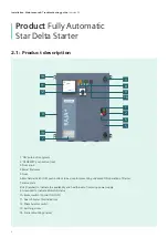
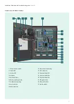
Page 1: ...Installation Maintenance Troubleshooting Guide For RAJA Agriculture Starters Controllers ...

Page 2: ...allation 2 5 Operating procedure in normal condition 2 6 Troubleshooting guidelines in case any incoming fault is present before switching ON the motor 2 7 Troubleshooting guidelines in fault condition when motor stops while it is in running condition 2 8 Troubleshooting guidelines in case any fault is at the load side ...

Page 3: ...preventing undesired ON operation of Starter 7 Name plate 8 LED amber to indicate the availability and healthiness of incoming power supply 9 Green LED to indicate Motor ON status 10 Rocker switch Control ON OFF 11 Dual VA meter For indication 12 Phase Selector switch 13 Earthing screw 14 Starter Mounting bracket 3 Installation Maintenance Troubleshooting guide Version 02 3 1 6 2 5 7 13 4 12 11 14...

Page 4: ... Line Contactor 9 Delta contactor 10 Thermal overload relay 11 Star contactor 12 Terminal block TB3 13 Terminal block TB2 14 Terminal block TB1 15 ON push button 16 OFF push button 17 Rocker switch 1 2 3 4 5 6 7 8 9 10 11 12 13 14 15 16 17 4 Inside view of FASD 1 Starter Installation Maintenance Troubleshooting guide Version 02 ...

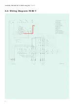
Page 5: ...2 2 Wiring Diagram FASD 1 Installation Maintenance Troubleshooting guide Version 02 5 ...

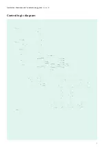
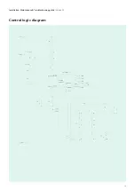
Page 6: ...Control logic diagram 6 Installation Maintenance Troubleshooting guide Version 02 ...

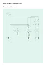
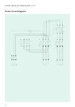
Page 7: ...Power circuit diagram 7 Installation Maintenance Troubleshooting guide Version 02 ...

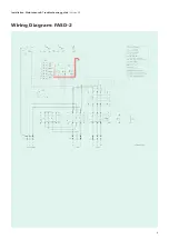
Page 8: ...8 Wiring Diagram FASD 2 Installation Maintenance Troubleshooting guide Version 02 ...

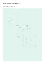
Page 9: ...9 Control logic diagram Installation Maintenance Troubleshooting guide Version 02 ...

Page 10: ...10 Power circuit diagram Installation Maintenance Troubleshooting guide Version 02 ...

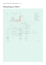
Page 11: ...Wiring Diagram FASD 3 Installation Maintenance Troubleshooting guide Version 02 11 ...

Page 12: ...Control logic diagram 12 Installation Maintenance Troubleshooting guide Version 02 ...

Page 13: ...Power circuit diagram 13 Installation Maintenance Troubleshooting guide Version 02 ...

Page 14: ... 12 5 20 7UG0613 0yy20 6 0 2 5 17 5 13 2 15 3TS33 3TS31 3UW5202 2B 12 5 20 7UG0613 0yy20 3TE7421 2BC26 1Axx 20 15 32 18 5 3TS33 3TS31 3UW5202 2B 12 5 20 7UG0613 0yy20 40A 6 0 2 5 3TE7421 2CC27 1AZ8 25 18 5 36 20 8 3TS35 3TS48 3US5600 2C8K 16 25 7UG0613 0yy20 63A 10 4 0 20 15 39 22 5 3TS35 3TS32 3US5600 2D8K 20 32 7UG0613 0yy20 10 6 0 30 22 45 26 3TS35 3TS33 3US5600 2D8K 20 32 7UG0613 0yy20 30 22 5...

Page 15: ...available then set the dial to approximately 6 8secs Installation Maintenance Troubleshooting guide Version 02 Overload relay setting For closer protection set the overload relay to actual phase current as measured by an ammeter In the absence of anammeter use the procedure given below Start the motor and let it run for 30 mins Then gradually reduce the relay settings till it trips Set the relay a...

Page 16: ...reen push button marked I Fig 3 Line current of R phase is indicated by Dual VA meter Note For FASD3 starter current indication in AV meter needs to be multiplied by 40 Indication of Motor ON can be seen on starter door through green LED For stopping the motor press Red push button marked O Fig 3 Reset Operation If the overload relay trips Reset manually Allow a reset time of approx 4 min Caution ...

Page 17: ...ng On Insulator M6 6 0 to 8 0Nm Table 10 Terminal torque values Sr No Type Size Torque 1 3TS30 32 M4 0 8 1 4Nm 2 3TS33 34 M4 1 0 1 5Nm 3 3TS35 36 M4 2 5 3 0Nm 4 3TS47 48 M6 4 6Nm 5 3TS49 50 M6 4 6Nm 6 3TS51 M6 6 8Nm 7 Terminal block 30A M4 0 8 1 4Nm 8 Terminal block 60A M5 1 5 2 1Nm 9 Terminal block 100A M6 2 5 3 0Nm 10 Contact block 3SB5 M3 5 0 8 1 2Nm 11 Aux terminal side add on of 3TS47 48 3TS5...

Page 18: ...OFF 4L Green LED turns OFF indicating that the motor is OFF 4M Amber LED indication remains continous ON 4N Switch OFF the 3 phase incoming main supply 4O Amber LED indication gets turned OFF indicating that there is no incoming main supply 2 5 Operating procedure in normal condition Starter operation Table 11 FASD starter operating sequence in normal condition LMR A Mode Manual Auto Bypass 4A 3ф ...

Page 19: ... 4B Switch ON the 3 Phase incoming main supply 4C Switch ON the rocker switch Customer may switch ON the starter directly after switching ON the 3 phase incoming supply irresepctive of Blinking status as there is only indication for incoming supply faults and no Protection in Bypass mode 4D Amber LED will start blinking for a period of 30sec 4E 30sec is the default setting which can vary from min ...

Page 20: ...ng terminal 2 5H Connect the phase sequence of all the phases correctly R phase to L1 Y phase to L2 B phase to L3 to the incoming main supply terminals of Terminal block TB1 Repeat the steps from 5A to 5E and then go to step no 5I If fault still exists then 3 5G Check the rated operational voltage of the starter in incoming terminal block TB1 between L1 L2 L2 L3 L1 L3 with suitable equipment e g m...

Page 21: ...Star Line contactor switches ON together initially then after 6sec depending upon the time setting of star delta timer star contactor switches OFF and Delta contactor switches ON 5L Green LED turns ON indicating that the motor is ON 21 2 LMR A Auto mode 5A Check the mode of LMR A if it is Auto mode Repeat steps from 5B to 5H 5I Amber LED will remain ON continously indicating that the fault is clea...

Page 22: ...de Refer Table no 12 Corrective action 2 6F to 6L Follow steps from 4B to 4I of Auto mode Refer Table no 11 6M Motor starts running again Starter Fault conditon Table 14 FASD starter operating sequence in fault condition 6A 6B 6C 6D 6E 6F 6G 6H 6J 6K 6L 6M 6I 3 LMR A Bypass mode As in Bypass mode there is no protection from the inconing supply faults however there may some conditions example menti...

Page 23: ...r current rating and adjust the overload relay setting dial as per the requirement b Single phasing at load side Overload relay tripped as inbuilt feature to protect from single phase faults Check the single phasing condition at Motor side terminal TB2 TB3 to Motor For both conditions restart the Starter after proper reset time of approx 4 min Steps to be followed Installation Maintenance Troubles...

Page 24: ...ple and helps customers achieve their business goals It helps our customers to thrive communities to progress and supports sustainable development to protect our planet for the next generation Creating environments that care siemens com smart infrastructure Subject to changes and errors The information given in this document only contains general descriptions and or performance features which may ...

Reviews: