background image

RCC10U Room Temperature Controller 

Technical Instructions 

for Two-pipe Fan Coil Units 

Document Number 155-712 


September 27, 2007 

Siemens Industry, Inc. 

Page 11


Specifications 

Power Supply 

Operating voltage 

120 Vac +10/-15% 

Frequency 

50/60 Hz 

Power consumption 

Maximum 10A 

Control Outputs  (Fan) 11, 10, 9 

120 Vac max./5 res./3.5 FLA/7.0 LRA 


(Valve) 7 

120 Vac max./5 res./3.5 FLA/7.0 LRA 


Signal Input 1 for return air sensor 

QAH11.1, Class 2 


NTC resistor 3K 

Ω @ 77°F (25°C) 

Signal Input 3 for changeover sensor 

QAH11.1, Class 2 


NTC resistor 3K 

Ω @ 77°F (25°C) 

Permissible number of thermostats 

Ten 


in parallel, Signal Input 3 

Status Input D1 and GND 
 

Contact sensing 

6 to 15 Vdc/3 to 6 mA 

Operating action  

Single-pole, Single-throw (SPST) 

Permissible cable length with copper 

262 feet (80 m) 


cable 16 AWG for connection to  


Terminals 1, 3, D1, and GND 

Operational Data 

Setpoint setting range 

50°F to 85°F (10°C to 30°C) 

Switching differential in Heating mode SDH  2°F or 7°F (1°C or 4°C) 
 

(selectable) 

Switching differential in Cooling mode SDC  1°F or 3.5°F (0.5°C or 2°C) 
 

(selectable) 

Setpoint (Energy Saving mode  ),  

61°F (16°C) 


heating 

Setpoint (Energy Saving mode  ),  

82°F (28°C) 


Cooling 

Setpoint (Freeze Protection 

)  

46°F (8°C) 

General Ambient 
Conditions 

Operation 
 

Temperature 

32°F to 122°F (0°C to 50°C) 


Humidity 

<95% rh 

Shipping and storage 
 

Temperature 

–13°F to 158°F (–25°C to 70°C) 


Humidity 

<95% rh 

Agency Approvals 

UL Listing 

UL 873 

cUL certification 

C22.2 No. 24-93 


Conforms to CE requirements 

Degree of housing protection 

NEMA 1 

General 

Connection terminals 

Solid wires or prepared standard wires 


2 × 16 AWG or 1 × 14 AWG 


Minimum 20 AWG 

Weight 

0.55 lb (0.25 kg) 

Housing color 
 

Cover 

White and gray 


Base 

Gray 

Degree of housing protection 

NEMA 1 

Summary of Contents for RCC10U

Page 1: ...c Heating Cooling changeover Operating modes Normal Energy Saving Freeze Protection and Off Operating mode changeover input for remote control Selectable control parameters Operating voltage 120 Vac Application Typical use Controlling room temperature in individual rooms that are heated or cooled with two pipe fan coil units Opening or closing a valve Switching a three speed fan Suitable for use i...

Page 2: ...cedure as specified CAUTION Equipment damage or loss of data may occur if you do not follow a procedure as specified Functions The controller measures the room temperature with its integrated sensor or external return air temperature sensor QAH11 1 if used and maintains the setpoint by delivering control commands to the two position on off valve The switching differential is adjustable it can be 2...

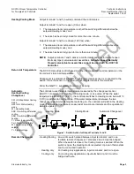
Page 3: ... QAH11 1 separately for return air sensing Automatic Heating Cooling Changeover CW Chilled Water Cooling mode HW Hot Water Heating mode M Operating mode SDC Switching differential cooling SDH Switching differential heating T Room temperature Tw Water temperature W Room temperature setpoint Y Signal voltage The controller uses the water temperature measured by the changeover sensor QAH11 1 to switc...

Page 4: ...holes around the perimeter of knob as required See Figure 2 Figure 2 Setpoint Limit Stops Operating Modes The following operating modes are available Normal Operating Mode Heating or Cooling mode with automatic changeover and with manually selected fan speed Low Medium High In Normal operation the controller maintains the adjusted setpoint Freeze Protection Mode The Freeze Protection function is a...

Page 5: ...ating Mode Changeover Switch A changeover switch can be connected to status input D1 GND When the switch closes its contact such as caused by an open window the operating mode will change from Normal operation to Energy Saving mode if DIP Switch No 2 is set to ON or from Normal operation to Standby if DIP Switch No 2 is set to OFF If the room temperature falls below 46 F 8 C and if DIP Switch No 4...

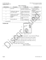
Page 6: ... for external operating mode changeover Changeover activated when contact of switch is closed NO 1 Changeover activated when contact of switch is open NC 4 Standby Freeze Protection function disabled Freeze Protection function enabled 5 Switching differential 2 F 1 C in Heating mode1 1 F 0 5 C in Cooling mode1 7 F 4 C in Heating mode 3 5 F 2 C in Cooling mode 1 Factory setting Construction 1 Stand...

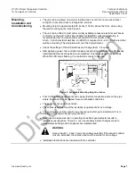
Page 7: ... if required After applying power the controller makes a reset during which the fan LED flashes indicating that the reset has been accomplished This takes about three seconds When the LED stops flashing the controller is ready to operate Figure 5 Acceptable Mounting Height in Inches Prior to fitting the changeover sensor apply thermal conductive paste on the pipe where the sensor is to be placed S...

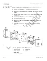
Page 8: ...iver 2 Lift the bottom of the controller from the controller base and push up to remove Figure 6 Controller Separation 3 Fasten the wall box adapter 3 to plaster ring 2 supplied by others using the four screws provided with the ARG70 4 Flex adapter mask 4 and snap in place inside wall box adapter 3 5 Pull wires through plaster ring 2 6 Fasten controller base 5 to wall box adapter assembly 3 and 4 ...

Page 9: ...Inc Page 9 4 inch 4 inch Electrical Wall Box Mounting Continued 7 Terminate wires per wiring instructions located above the terminal block Figure 8 Wiring Termination 8 Reattach the controller to the controller base 9 Secure by tightening the screw at the bottom of the controller Figure 9 Controller Reattachment The installation is now complete ...

Page 10: ...ler from the controller base and push up to remove See Figure 6 3 Fasten the wall box adapter 3 to plaster ring 2 supplied by others using the two screws provided 4 Flex adapter mask 4 and snap in place inside wall box adapter 3 5 Pull wires through plaster ring 2 6 Fasten controller base 5 to wall box adapter assembly 3 and 4 with the two screws provided 7 Follow Steps 7 through 9 of the 4 inch 4...

Page 11: ...th copper 262 feet 80 m cable 16 AWG for connection to Terminals 1 3 D1 and GND Operational Data Setpoint setting range 50 F to 85 F 10 C to 30 C Switching differential in Heating mode SDH 2 F or 7 F 1 C or 4 C selectable Switching differential in Cooling mode SDC 1 F or 3 5 F 0 5 C or 2 C selectable Setpoint Energy Saving mode 61 F 16 C heating Setpoint Energy Saving mode 82 F 28 C Cooling Setpoi...

Page 12: ...Control output Valve 120 Vac 9 Control output Fan speed III 120 Vac High 10 Control output Fan speed II 120 Vac Medium 11 Control output Fan speed I 120 Vac Low D1 GND Status input for potential free operating mode changeover switch operating action can be selected Figure 11 Wiring Terminals Wiring Diagram B1 Return air temperature sensor QAH11 1 B2 Changeover sensor QAH11 1 G Operating voltage 12...

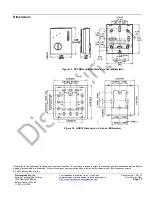
Page 13: ...r respective owners 2007 Siemens Industry Inc Siemens Industry Inc Building Technologies Division 1000 Deerfield Parkway Buffalo Grove IL 60089 1 847 215 1000 Your feedback is important to us If you have comments about this document please send them to SBT_technical editor us sbt siemens com Document No 155 712 Printed in the USA Page 13 Dimensions Figure 13 RCC10U and Base Plate in Inches Millime...

Reviews: