RCC10U Room Temperature Controller
Technical Instructions
for Two-pipe Fan Coil Units
Document Number 155-712
September 27, 2007
Siemens Industry, Inc.
Page 7
Mounting,
Installation and
Commissioning
•
The unit can be located on a wall or inside a fan coil unit. Do not mount in direct
sunlight or near other heat or refrigeration sources.
•
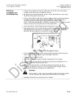
Mounting height is approximately 60 inches (150 cm) above the floor, when using
the wall mounting option. See Figure 5.
•
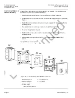
The unit can be fitted to most commercially available recessed electrical wall boxes
or directly on the wall. A Wall Box Adapter Kit (ARG70), ordered separately, is
recommended but not required to mount an RCC10U controller to a
2-inch × 4-inch electrical wall box. An ARG70 is required for 4-inch × 4-inch electrical
wall box mounting. The wall plate will cover the drywall cutout.
•
Check the settings of the DIP switches and change them, if required.
•
After applying power, the controller makes a reset during which the fan LED flashes
indicating that the reset has been accomplished. This takes about three seconds.
When the LED stops flashing, the controller is ready to operate.
Figure 5. Acceptable Mounting Height in Inches.
•
Prior to fitting the changeover sensor, apply thermal conductive paste on the pipe
where the sensor is to be placed. Secure with plastic cable ties.
•
The sensor is not position sensitive.
•
The cables used must meet the insulation requirements for live voltage.
•
The control valve is fully open for one minute upon start-up to determine if it is in
Heating or Cooling mode (purging function).
•
User input via setpoint knob or operating mode/fan speed selector results in
instantaneous response. There is a one-minute delay before changes made to
temperature sensing and changeover are implemented.
WARNING:
Sensor inputs
1, 2 and 3 carry live voltage potential. If the sensor’s cables
must be extended, the cables used must be suited for live voltage.
•
Installation Instructions are included with the controller.


