background image

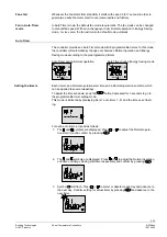
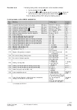
The controller will leave the programmable timer setting mode if no button is pressed 
within 20 seconds. All changes made after the last press of 

 button will not be 

saved. 
Press the 

 button to sequentially review the 8 timers. 

View the timers 


Default timer setting 

Timers A1…A4 have the following default setting: 

Day/s 

Time when controller is in Normal operation   

Mo (1) – Fr (5) 

06:30 – 08:30 (A1) 

17:30 – 22:30 (A2) 

Sa (6) 

08:00 – 23:00 (A3) 

Su (7) 

08:00 – 22:30 (A4) 


 - During the remaining time, controller is in Energy Saving mode 
 - Timers A5…A8 are free, no default setting 

 
The setting of these timers can be changed to suit individual needs. The default setting 
can be reloaded any time: 

Reload default timer 
setting 

1. 

Set the controller to Standby  . 

2. 

Press   and   simultaneously for 3 seconds. Release them and, within 2 seconds, 

press 2 times 

Then, the display will show “8888“ during the reloading process. 
 

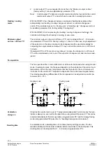
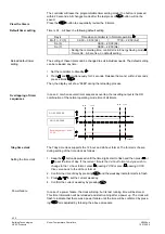
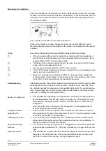
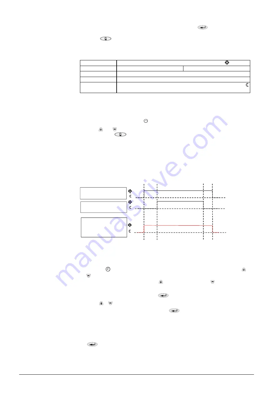
In case 2, or when several timer sequences overlap, the resulting output is the OR 
combination of the normal operating mode time of all timers. 

Overlapping of timer 
sequences 

A1=09:00-22:00 

A2=12:00-20:00 

09:00 

12:00 

20:00 

22:00 


3058D04

Resulting output = 09:00-
22:00 


The 7day-time clock supports the 12-hour and 24-hour format. The format is chosen 
during setting of the time clock as follows: 

7day-time clock 

1. Keep the   button depressed until the time digits start to flash and then press   or 

 to set the time of day. 

If the current  time is the 24-hour format and you wish to 

change to the 12-hour format, press   passing 23:59 or press   passing 00:00. 
Vice versa back to the 24-hour format

Setting the time clock 

2.  Confirm the time of day by pressing 

 and the weekday indicator starts to flash. 

3. Press   or  to set the current weekday. 

4.  Confirm the current weekday by pressing 


Power failure 

In case of a power failure, the clock will stop, but its last running time will be stored. 
This time information will be reloaded and start running after a power up. The clock will 
flash to indicate that there was a power failure until the time will be confirmed by press-
ing 

 or readjusted by folowing the above procedure. 


6/15 

Building Technologies 

Room Temperature Controllers 

N3058en 

HVAC Products 


10.01.2006 

Summary of Contents for RDF210

Page 1: ...ntrol Automatic or manual 8 programmable timers Adjustable commissioning and control parameters Optional display of room temperature or setpoint Minimum and maximum setpoint limitation Operating voltage AC 230 V Additional features of RDF210 Automatic heating cooling changeover Input for heating cooling changeover or return air temperature sensor Additional features of RDF210 2 Manual heating cool...

Page 2: ...l Output for 2 position on off valve actuator or 1 stage compressor Optional with infrared remote control only with RDF210 IR Controller Temperature control The controller acquires the room temperature via its built in sensor and maintains the setpoint by delivering 2 position valve control commands or compressor output com mands With the RDF210 an external room temperature sensor QAA32 or externa...

Page 3: ...f air circulation in Energy Saving mode the fan can be kept running all the time e g in apartments or shops during unoccupied periods when setting parameter P20 ON in dead zone In this case the fan keeps running at minimum fan speed 1 Avoiding damage due to moisture Control sequences Used in conjunction with a valve either for heating cooling with changeover heating only or cooling only Water base...

Page 4: ... on off time of Y11 will be maintained as set even if the setpoint or changeover mode has been read justed Fan operation The fan operates either in automatic mode or at the selected speed when using manual mode In automatic mode the fan speed depends on the setpoint and the current room temperature When the room temperature reaches the setpoint the control valve will close and the fan switch off T...

Page 5: ...ode o C 1 AUTO o C 1 AUTO Setting the timers Each timer has a Normal operation start time and a Normal operation end time which can be applied to several weekdays To adjust the time schedule keep the button depressed for 3 seconds to go to the programmable timer setting mode This mode is indicated by displaying Ax x auto timer 1 8 and the time xx xx flash ing For each auto timer proceed as follows...

Page 6: ...operating mode time of all timers Overlapping of timer sequences A1 09 00 22 00 A2 12 00 20 00 09 00 12 00 20 00 22 00 3058D04 Resulting output 09 00 22 00 The 7day time clock supports the 12 hour and 24 hour format The format is chosen during setting of the time clock as follows 7day time clock 1 Keep the button depressed until the time digits start to flash and then press or to set the time of d...

Page 7: ...changeover The QAH11 1 cable temperature sensor for automatic heating cooling changeover can be replaced by an external switch suited for mains voltage for manual remote change over 3058Z03 B1 M T B1 M QAH11 1 T C Contact open Æ heating mode Contact closed Æ cooling mode With parameter P99 diagnostic value automatic heating cooling changeover can be checked External room or return air temperature ...

Page 8: ...l fan speed Using parameter P25 infrared remote control can be disabled Control parameters With the RDF210 and RDF210 2 a number of control parameters can be readjusted to optimize the control performance These parameters can also be set during operation without opening the unit In the event of a power failure all control parameter settings will be maintained Parameter settings The parameters can ...

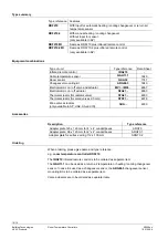
Page 9: ...DC2 0 5 4K 1 K P12 Switching differential fan speed 3 in heating mode SDH3 0 5 4K 1 K P13 Switching differential fan speed 3 in cooling mode SDC3 0 5 4K 1 K P14 Dwelling time of auto fan speeds 1 5 minutes 2 min P15 Minimum output on time Y11 1 10 minutes 1 min P16 Minimum output off time Y11 1 10 minutes 1 min P17 Selection of C or F C or F C P18 Display of temperature or setpoint OFF Setpoint ON...

Page 10: ...diator valve STA21 4893 Thermal actuator for small valves 2 5 mm STP21 4878 Zone valve actuators only available in AP UAE SA and IN SUA 4830 Accessories Description Type reference Adapter plate 120 x 120 mm for 4 x 4 conduit boxes ARG70 Adapter plate 96 x 120 mm for 2 x 4 conduit boxes ARG70 1 Adapter plate for surface wiring 112 x 130 mm ARG70 2 Ordering When ordering please give name and type re...

Page 11: ...eekday 1 7 1 Monday 7 Sunday 4 Current time of day 5 Standby fan mode status Standby mode AUTO Auto fan active fan speed low medium high 6 in cooling mode in heating mode 7 AUTO Auto Timer mode Normal operation Energy Saving mode 8 Buttons for adjusting the setpoints control parameters and time of day 9 Button for changing fan operation and Standby 10 Button operating mode AUTO Normal operation Au...

Page 12: ...ndicating that the reset has been correctly made This takes about 3 seconds Then the controller is ready for commissioning by qualified HVAC staff The control parame ters of the controller can be set to ensure optimum performance of the whole system also refer to Setting the control parameters Only with RDF210 Depending on the application the heating cooling mode must be set via parameter P22 Fact...

Page 13: ...points Normal operation Energy Saving in heating cooling mode Standby heating and cooling mode 20 C 16 C 28 C OFF Built in room temperature sensor Measuring range Accuracy at 25 C Temperature calibration range 0 49 C 0 5 K 3 0 K Resolution of settings and display Setpoints Current temperature value displayed 0 5 C 0 5 C Operational data Operation Climatic conditions Temperature Humidity to IEC 721...

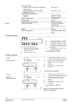
Page 14: ...mpressor Y12 Control output Valve AC 230 V N C for normally open valves Only with RDF210 or RDF210 IR Connection diagrams Application 2 pipe fan coil units L N QAA32 QAH11 1 ARG86 3 10 A L B1 M N Q1 Q2 Q3 Y11 N 4 2 A max 4 2 A max I II III AC 230 V Y12 RDF210 3058A01 B1 B2 M1 Y1 N1 B1 Return air temperature sensor QAH11 1 or external room temperature sensor QAA32 B2 Changeover sensor temperature s...

Page 15: ...04 Mounting base 28 28 35 30 10 15 94 85 28 7 30 4 2 5 21 85 34 15 120 3 31 65 24 35 11 8 28 28 4 3058Z05 15 15 Building Technologies Room Temperature Controllers N3058en 2006 Siemens Switzerland Ltd Subject to alteration HVAC Products 10 01 2006 ...

Reviews: