Technical Instructions
RDX42.22U Room Temperature Controller with LCD
Document Number 155-747
March 13, 2008
Page 10
Siemens Industry, Inc.
Wiring Terminals
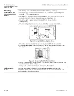
Figure 5. Wiring.
1,2,3
Operating voltage, 24 Vac Neg
4
Operating voltage, 24 Vac Pos
5
Cooling output, NO contact
6
Cooling output, NC contact
7
Auxiliary heating output
8
Measuring neutral remote sensor
9
Remote temperature sensor
(QAH11.1)
10
Heating output, NO contact
11
Heating output, NC contact
12
Fan output at single speed
D1, GND Signal input for potential- free
operating mode changeover
Wiring Diagrams
Figure 6. Four-pipe System Wiring.
Figure 7. Heat Pump Wiring.
6
Cooling output NC contact
5
Cooling output NO contact
11
Heating output NC contact
10
Heating output NO contact
6
Cooling output NC contact for
reversing valve
5
Cooling output NO contact for
compressor
11
Heating output NC contact for
reversing valve
10
Heating output NO contact for
compressor
NOTE:
Outputs 5 and 10 must be wired
together for compressor control


