background image

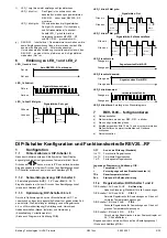
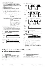
1.1.5  Periodischer Pumpenlauf: DIP-Schalter 5 

Diese Funktion schützt die Pumpe während längeren AUS-
Perioden vor einem möglichen Festsitzen. Der periodische 
Pumpenlauf wird alle 24 Stunden um 12:00 Uhr für eine Minute 
aktiviert (auf dem Display erscheint während des aktiven 
Pumpenlaufs das Heizsymbol 

periodischer Pumpenlauf EIN. 

DIP-Schalter 5 AUS (Standard) 
DIP-Schalter 5 EIN 
Nur anwendbar bei angesteuerter Umwälzpumpe! 
 

1.1.6  Regler-Wirksinn DIP-Schalter 4 

DIP-Schalter 4 AUS (Standard) für Heizen 
DIP-Schalter 4 EIN für Kühlen 

2 Funktionskontrolle 

a)  Anzeige kontrollieren. Erscheint keine Anzeige, muss der Einbau 

und die Funktion der Batterien geprüft werden 

b)  Betriebsart Komfort  


c) 

Temperatursollwert auf 29 °C einstellen (siehe 
Bedienungsanleitung) 

d)  Das Relais und somit das Stellgerät müssen spätestens nach 

einer Minute schalten. Das Symbol 

 erscheint auf dem 

Display. Ist dies nicht der Fall: 

  Stellgerät und Verdrahtung prüfen 

  Eventuell ist die Raumtemperatur höher als 29 °C 

e)  Sollwerttemperatur wieder auf den ursprünglichen Wert 

zurückstellen (Standardwert 19 °C oder eigene Einstellung) 

f) Gewünschte 

Betriebsart 

wählen 

3 Reset 


Taste hinter der Nadelöffnung mindestens eine Sekunde drücken: 
Dadurch werden die benutzerspezifischen Einstellungen auf ihre 
Standardwerte zurückgesetzt. 
Die Uhr beginnt bei 12:00. Während der Resetzeit leuchten alle 
Anzeigefelder des Displays, und können so überprüft werden. 

4 Hinweise 

  Der Regler gehört zur Softwareklasse A und ist für den Gebrauch in 

einer Umgebung mit normalem Verschmutzungsgrad vorgesehen 

  REV200…RF/SET ist ein Apparate Set bestehend aus 

elektronischem Raumtemperaturregler mit Wochenschaltuhr und 
Funksender (REV200…RF) und Funkempfänger (REV-R.03…). 


  Mounting and siting notes REV200...RF and REV-R.03...

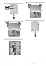
1 Siting 

the 

units 

1.1 

REV200…RF and REV-R.03… 


The units should be sited such that transmited and received 
signals will be disturbed as little as possible. For this reason, the 
following points should be observed with both the REV200…RF 
and REV-R.03…: 

  Do not mount the units on metal surfaces 

  Do not mount the units near electrical wires or electronic 

equipment such as PCs, TV sets, microwave equipment, 
etc. 

  Do not mount the units in the vicinity of large metal 

structures or other construction elements with fine metal 
meshes like special glass or special concrete 


The distance between controller/transmitter and receiver 
should not exceed 20 m or 2 floors. 

1.2 REV200…RF 

(controller/transmitter) 


The controller / transmitter should be mounted in the main living 
room (wall mounting, free standing with stand) 


The REV200…RF should be located such that it can acquire the 
room temperature as accurately as possible, without getting 
affected by direct solar radiation or other heat or refrigeration 
sources. 

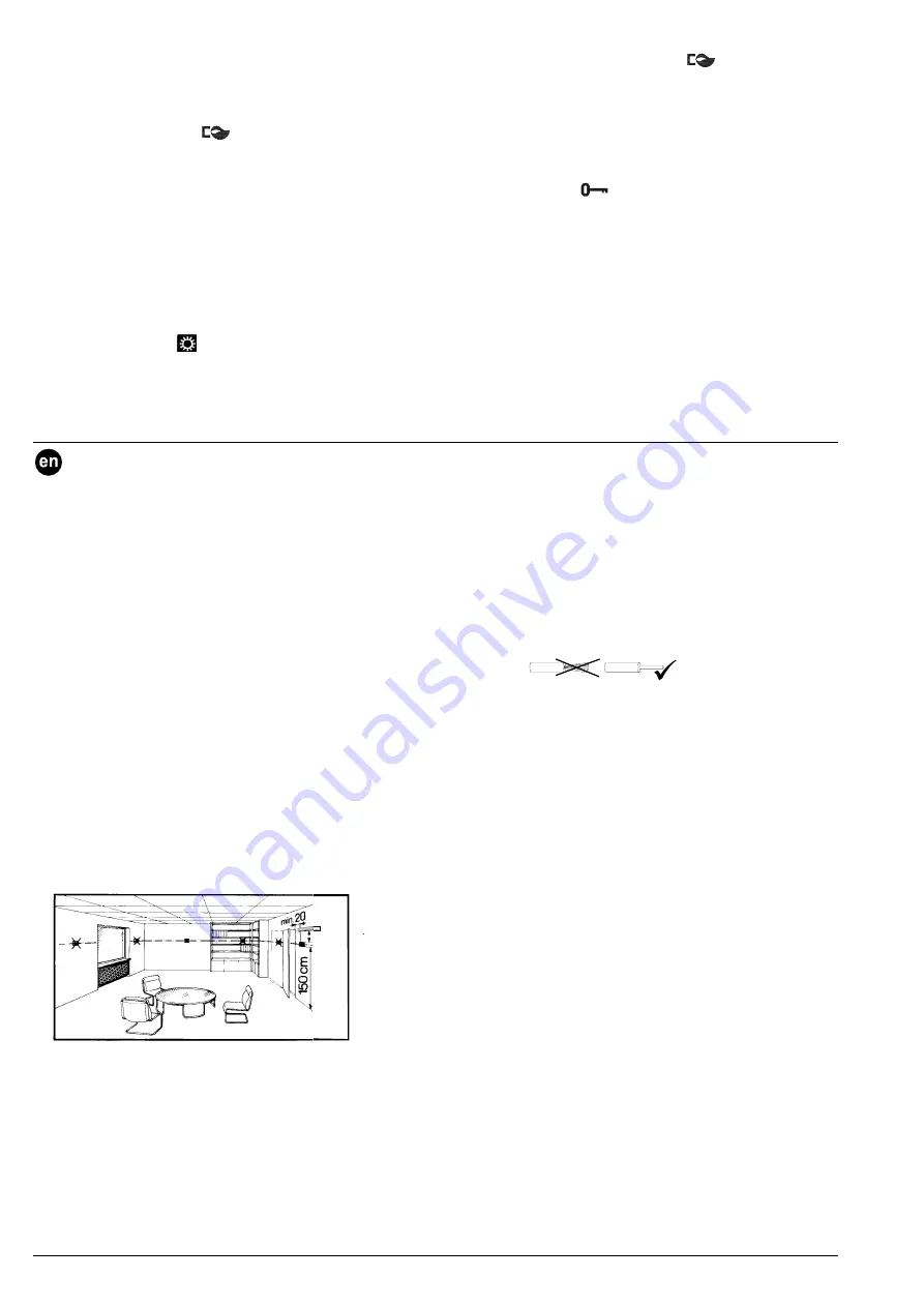
Siting note for wall mounting: 

min. 

10 cm

22

6

1Z

0

3


1.3 REV-R.03… 

(receiver) 


The receiver and switching unit should preferably be mounted 
near the actuating device 


Make certain that the mounting location is dry and protected 
from splash water 


The unit can be fitted to most commercially available recessed 
conduit boxes or directly on the wall. 


2 Check 

wiring 

For the electrical connections, refer to “Connection diagram“. 


Note:  Do not use stranded wires, only solid wires or 


stranded wires with ferrules. 


3 Notes 


The local regulations for electrical installations must be 
complied with 


If the reference room is equipped with thermostatic radiator 
valves, they must be set to their fully open position 


In the event of a power failure at the REV-R.03…, the relay will 
be deenergized. 


If in normal operation REV-R.03… does receive for more than  
25 minutes a very weak or no control telegram from 
REV200…RF, LED_1 starts to flash in red. 
If control telegram is still understood correctly, receiver 
continues with normal operation. If control telegram is not 
understood anymore, relay remains in last position being 
switched to before. 
As soon as REV-R.03… does receive any correct control 
telegram from REV200…RF again, receiver continuous with 
normal operation 


In case of error, REV-R.03… switches off relay approximately  
60 minutes after reception of last correct control telegram.  
The controlled device is also switched off and LED_1 flashes  
in red. 
As soon as REV-R.03… does receive any correct control 
telegram from REV200…RF again, receiver continuous with 
normal operation 


6/30 

09.02.2007 

G2214xx 


Building Technologies / HVAC Products 

Summary of Contents for REV-R.03 Series

Page 1: ... 2212Z19 3 2212Z20 4 2212Z21 5 2212Z23 6 2211Z24 7 2211Z25 8 SIEMENS REV200 www landisstaefa com rev200 2212Z28 9 2212Z29 10 2211Z30 REV200RF SET REV200SRF SET Building Technologies HVAC Products G2214xx 09 02 2007 1 30 ...

Page 2: ... 2 2252D01 16 3 1 4h C 1 2h C 1h C P 1 2 1 1 1 Pon 20 C T1 1 h h h TRx h h h h h h h h h 1 h C CAL off F 2211Z05 CAL on Werkseinstellungen Factory settings Réglages usine Impostazioni di fabbrica Ajustes fábrica Fabrieksinstelling Tovární nastavení Fabriksindstilling Palautus Fabriksinställning Επαναφορά εργοστασ ON 1 3 4 2 2211Z32 5 6 7 8 9 2 30 09 02 2007 G2214xx Building Technologies HVAC Produ...

Page 3: ...12 13 14 15 LED_1 LED_2 REV R 03 16 REV R 03 REV R 03 Building Technologies HVAC Products G2214xx 09 02 2007 3 30 ...

Page 4: ...setzung RF Set 1 REV200 RF einschalten Schwarzen Isolierstreifen entfernen Bild 7 Sobald der Isolier streifen am Batteriekontakt entfernt wird ist das Gerät in Betrieb 2 REV R 03 provisorisch montieren Wenn möglich den Empfänger zuerst provisorisch montieren z B mit Doppelklebeband damit später die beste Empfangs position ermittelt werden kann Siehe Punkt 5 Beste Empfangsposition finden REV R 03 k...

Page 5: ...DIP Schalter 3 2 Einstellmöglichkeiten AUS 3 29 C oder EIN 16 29 C Eingabe speichern mit einem Druck auf den Bestätigungsknopf siehe auch Abbildung 11 B 1 1 3 Optimierung DIP Schalter 6 bis 8 Durch die Optimierung wird nur der Einschaltzeitpunkt P 1 so vorverschoben dass der eingestellte Sollwert zur gewünschten Zeit erreicht wird Die Einstellung ist abhängig von der Regelstrecke d h von Wärmeüber...

Page 6: ...wires or electronic equipment such as PCs TV sets microwave equipment etc Do not mount the units in the vicinity of large metal structures or other construction elements with fine metal meshes like special glass or special concrete The distance between controller transmitter and receiver should not exceed 20 m or 2 floors 1 2 REV200 RF controller transmitter The controller transmitter should be mo...

Page 7: ...g to Fig 1 to 3 for wall mount refer to Figs 4 to 10 for set up with stand click the stand to the backside of base Also refer to Mounting and siting notes REV200 RF and REV R 03 5 Find location of best RF reception a Switch off power at REV R 03 b Switch on REV200 RF site at prefered location and press override button Test for about 4 seconds REV200 RF transmits test telegrams every 2 seconds Tran...

Page 8: ...ariations DIP switch 1 ON and DIP switch 2 OFF PID 6 Fast controlled systems for situations with great temperature variations DIP switch 1 ON and DIP switch 2 ON 2 Pt Difficult controlled systems proper on off controller with a switching differential of 0 5 C also refer to Fig 11 A 1 1 5 Periodic pump run DIP switch 5 This function protects the pump against seizing during longer off periods Period...

Page 9: ... environ 60 minutes après réception du dernier télégramme correct L appareil commandé est arrêté et la LED_1 clignote en rouge Dès que la réception redevient correcte le récepteur fonctionne à nouveau normalement Mise en service du kit RF 1 Mise sous tension du REV200 RF Retirer la bande isolante noire Fig 7 Dès que la bande isolante est retirée du contact des piles l appareil se met en marche 2 M...

Page 10: ...ouge LED_1 clignote 3 fois en vert Qualité du signal très bonne LED_1 clignote 2 fois en vert LED_1 clignote 1 fois en vert LED_2 orange ne s allume pas LED_2 reste allumée en permanence LED_2 clignote en permanence Clignotement bref réception d un télégramme de commande 7 Montage définitif du REV R 03 a Couper le courant b Marquer l emplacement du REV R 03 c Débrancher au besoin le câblage d Mont...

Page 11: ...câblage Vérifier que la température ambiante n est pas supérieure à 29 C e Remettre la consigne de température sur la valeur initiale valeur par défaut 19 C ou réglage personnalisé f Sélectionner le régime souhaité 3 Réinitialisation Reset Appuyer pendant une seconde minimum sur la touche marquée reset trou d épingle les réglages utilisateur sont ramenés aux valeurs standard Pendant le temps de ré...

Page 12: ...comando è eccitato e quindi il dispositivo da comandare è acceso h Se il LED_2 arancione rimane spento il relé di comando è diseccitato e quindi il dispositivo da comandare è spento i In funzione dello stato operativo il trasmettitore REV200 RF invia il segnale di comando ON o OFF ogni 3 minuti quindi il relé potrebbe essere comandato con un ritardo entro tale tempo j Se il ricevitore REV R 03 non...

Page 13: ...ianti con regolazione rapida per situazioni con ampie e frequenti variazioni di temperatura DIP switch 1 ON e DIP switch 2 ON 2 Pt Impianti con regolazione difficile comando on off con differenziale di 0 5 C vedi Fig 11 A 1 1 5 Funzionamento periodico della pompa DIP switch 5 Questa funzione protegge la pompa di circolazione da un eventuale grippaggio dovuto a lunghi periodi di fermo Il funzioname...

Page 14: ...rol correcta El equipo controlado también se desconecta y el LED_1 parpadea en rojo En cuanto el REV R 03 vuelve a recibir cualquier señal inteligible desde el REV200 RF el receptor continúa con la operación normal Puesta en servicio del receptor RF 1 Conecte el REV200 RF Retire la lengüeta de protección de las pilas ver Fig 7 En cuanto se retira la lengüeta la unidad comienza a funcionar 2 Montaj...

Page 15: ... naranja Recepción de señal de control 7 Fin del montaje del REV R 03 a Desconecte la alimentación b Marque la ubicación actual del REV R 03 c Si fuera necesario libere el cableado d Monte el receptor según las indicaciones de las Figs 12 a 14 cablee de nuevo y cierre la carcasa e Conecte la alimentación Configuración de microinterruptores DIP y verificación de funciones del REV200 RF 1 Configurac...

Page 16: ... 19 C o su ajuste individual 3 Reset Parámetros introducidos por el usuario Pulse el botón que hay en la abertura trasera durante al menos un segundo Esto reestablece los valores por defecto en los parámetros introducidos por el usuario El reloj arranca a las 12 00 Durante el tiempo de reajuste todas los segmentos de la pantalla se iluminan permitiendo su verificación 4 Notas El Controlador está c...

Page 17: ... en kort g Als de oranje LED_2 constant brandt is het relais aangetrokken bestuurde apparaat AAN h Als de oranje LED_2 niet brandt is het relais afgevallen bestuurde apparaat UIT i De REV200 RF herhaalt elke 3 minuten afhankelijk van de status het AAN of UIT signaal Daardoor wordt uiterlijk na 3 Minuten het relais weer overeenkomstig het commando AAN UIT geschakeld j Als de REV R 03 gedurende 60 m...

Page 18: ...peratuurschommelingen DIP schak 1 IN en 2 IN 2 Pt Voor moeilijke regeltrajecten echte tweepuntsregelaar met 0 5 C schakeldifferentie De instelling opslaan met een druk op de bevestigingstoets zie afb 11 A 1 1 5 Periodiek draaien van de pomp DIP schakelaar 5 Deze functie beveiligt de pomp bij lange UIT perioden tegen een eventueel vastzitten Het periodiek draaien van de pomp wordt iedere 24 uur om ...

Page 19: ... Ovládané zařízení je vypnuté a LED_1 bliká červeně Jakmile přijímač REV R 03 obdrží opět korektní řídicí telegram z vysílače REV200 RF vrátí se do normálního provozu Uvedení do provozu vysílače REV200 RF a přijímače REV R 03 1 Zapnutí REV200 RF Odstraňte izolační pásek z kontaktu baterií Viz obrázek 7 Jakmile je odstraněn izolační pásek přístroj se uvede do provozu 2 Provizorně namontujte REV R 0...

Page 20: ...to kde je momentálně regulátor namontován c Pokud je to nutné uvolněte kabeláž d Namontujte dle obr 12 až 14 přijímač na označené místo definitivně připojte vodiče a uzavřete kryt přístroje e Zapněte napájení Uvedení do provozu regulátoru vysílače REV200 RF 1 Přizpůsobení dané aplikaci 1 1 Kalibrace teplotního čidla DIP spínač 9 Po aktivaci DIP spínače se zobrazí na displeji symbol CAL a začne bli...

Page 21: ...ní Tovární nastavení DIP spínač 4 ON chlazení viz obrázek 11 C 2 Kontrola funkce a Zkontrolujte displej Jestliže se nic nezobrazuje zkontrolujte správné vložení a stav baterií b Nastavte provoz na komfortní teplotu c Pokud je regulátor v režimu vytápění nastavte žádanou teplotu na 29 C d Výstupní relé a tudíž regulované zařízení musí reagovat nejdéle 1 minutu po zobrazení symbolu na displeji Pokud...

Page 22: ...nen virheetön ohjaussähke on vastaanotettu Ohjattu laite kytketään pois päältä ja LED_1 vilkkuu punaisena Heti kun REV R 03 saa jälleen virheettömiä ohjaussähkeitä REV200 RF stä vastaanotin jatkaa normaalia toimintaansa Käyttöönotto RF Set 1 Kytke REV200 RF päälle Irrota musta eristysliuska kuva 7 Heti kun eristysliuska on irrotettu pariston koskettimesta laite alkaa toimia 2 Asenna REV R 03 välia...

Page 23: ... 14 mukaisesti aiemmin mer kitsemääsi paikkaan johdota se valmiiksi ja sulje kotelo e Kytke verkkojännite päälle DIP kytkinten konfigurointi ja REV200 RF n toimintatestaus 1 Konfigurointi 1 1 Anturin kalibrointi DIP kytkin 9 Kun DIP kytkin on aktivoitu näytöllä näkyy CAL symboli ja huoneläm pötilan senhetkinen mittausarvo vilkkuu Painamalla painikkeita arvo voidaan uudelleenkalibroida maks 2 C Tal...

Page 24: ...ch mottagning utan störningar kan garanteras Följande punkter skall beaktas såväl för REV200 RF som för REV R 03 montera inte enheten på metallytor ej nära elektriska ledningar och utrustning såsom PC TV och mikrovågsapparater o s v ej nära stora järndelar eller byggelement med finmaskiga metallgaller såsom specialglas eller specialbetong Avståndet mellan regulator sändare och mottagaren får inte ...

Page 25: ...a ifrån matningsspänningen till REV R 03 b Koppla på REV200 RF placera den vid önskad plats och tryck Test knappen under ca 4 sekunder REV200 RF sänder ett testmeddelande varannan sekund Sändningen av testmeddelanden stoppas automatiskt efter 10 min eller genom en kort tryckning av Test knappen c Koppla på matningsspänningen till REV R 03 d Kontrollera båda LED på REV R 03 från 2 till 3 meters avs...

Page 26: ...riftsätt värme kyla DIP omkopplare 4 DIP omkopplare 4 deaktiverad standard för värme DIP omkopplare 4 aktiverad för kyla se bild 11 C 2 Funktionskontroll a Kontrollera displayen Om ingen indikering visas kontrollera monteringen och batteriernas funktion b Driftsätt Komfort c Sätt temperaturbörvärde på 29 C se betjäningsinstruktion d Reläet och således styrdonet måste aktiveras senast efter 1 minut...

Page 27: ...ον τρόπο εκπαιδευτικής λειτουργίας το πολύ για 25 λεπτά Εάν σε αυτό το διάστηµα δε ληφθεί εκπαιδευτικό σήµα από τον REV200 RF επαναλάβετε τα βήµατα b και c εκ νέου e Πιέστε το πλήκτρο Learn του REV200 RF για περίπου 4 δευτερόλεπτα Εκπέµπεται το εκπαιδευτικό σήµα f Εάν ο REV R 03 λάβει το εκπαιδευτικό σήµα το πορτοκαλί LED_2 αρχίζει να αναβοσβήνει γρήγορα µε σύντοµες αναλαµπές g Εάν το πορτοκαλί LE...

Page 28: ...ου µέγεθος µόνωση και τα δεδοµένα του συστήµατος µέγεθος λέβητα θερµοκρασία προσαγωγής επίσης ανατρέξτε στ σχήµα 11 E OFF Καµία επίδραση εργοστασιακή ρύθµιση h C Για γρήγορα ελεγχόµενα συστήµατα h C Για κανονικά ελεγχόµενα συστήµατα 1 h C Για αργά ελεγχόµενα συστήµατα Επεξήγηση συµβόλων σχήµατος 11 E T Θερµοκρασία C t Χρόνος µετατόπισης ανοίγµατος h TRx Πραγµατική θερµοκρασία χώρου Pon Σηµείο έναρ...

Page 29: ...αρχική της τιµή τυποποιηµένη τιµή 19 C ή οποιαδήποτε δική σας ρύθµιση 3 Επαναφορά Εργ σιακών τιµών εδοµένα χρήστη Πιέστε το κρυφό πλήκτρο που βρίσκεται στη δεξιά πλευρά της οθόνης για τουλάχιστον τρία 3 δευτερόλεπτα µε τον τρόπο αυτό επαναφέρετε τις ρυθµίσεις χρήστη στις προεπιλεγµένες τιµές τους οι ρυθµίσεις που έγιναν σε επίπεδο µηχανικού θέρµανσης δεν θα επηρεαστούν Το ρολόι αρχίζει να λειτουργ...

Page 30: ...AC 24 250 V L1 Contacto de trabajo NA 24 250 V CA 6 2 5 A Maakcontact AC 24 250 V 6 2 5 A Spínací kontakt AC 24 250 V 6 2 5 A L2 Contacto de trabajo NC 24 250 V CA 6 2 5 A Verbreekcontact AC 24 250 V 6 2 5 A Rozpínací kontakt AC 24 250 V 6 2 5 A M1 Bomba circulación Circulatiepomp Oběhové čerpadlo N Neutro Nul Nula Nx Neutro Nul Nula N2 Receptor REV R 03 Ontvanger REV R 03 Přijímač REV R 03 Y1 Uni...

Reviews: