Initial Startup
It is assumed that the steps in chapters 1 to 4 have been followed. Check the connection of the auxiliary
power supply. 7SR5 devices have universal power-supply unit designs (Between DC 24 V and DC 250 V,
AC 100 V and AC 230 V auxiliary voltage range).
Ensure that the correct auxiliary supply voltage and polarity is applied. Before making any connections, the
device must be grounded.
See the relevant scheme diagrams in the device manual for the following relay connection terminals:
•
B22 terminal for + or L polarity
•
B24 terminal for – or N polarity
•
B28 terminal for Ground (Earthed)
After successful testing of the voltage source, the device can be switched on.
The device is now energized with the
Device Not Configured
message on it’s LCD display if it has not
been configured. The display of the message cannot be disabled as the act of changing any parameter or
loading a user configuration will automatically turn it off.
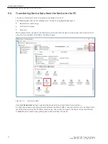
Afterwards, configuration can be sent to the device with Reydisp Manager 2 by reading the information in
5.4 Transferring Device Data from the Device to the PC
Settings and Configuration
Select the required relay configuration and settings for the application. If more than 1 settings group is to be
used for the application, it may be necessary to test both groups and also to test operation of the change
mechanism.
When using settings groups it is important to remember that the relay need not necessarily be operating
according to the settings that are currently being displayed on the device screen. There is an Active Settings
Group on which the relay operates and an Edit/View Settings Group which is visible on the display and which
can be changed from the fascia keys. This allows the settings in 1 group to be altered from the relay fascia
while the protection continues to operate on a different unaffected group. The Active Settings Group and the
Edit Settings Group are selected in the
Configuration Device
menu.
The currently Active Group and the group currently Viewed are shown at the top of the display in the
Settings
display screen. If the View Group is not shown at the top of the display, this indicates that the setting is
common to all groups.
CT/VT ratio, I/O mapping and other settings which are directly related to hardware are common to all groups. If
the relay is allowed to trip during testing then the instruments display will be interrupted and replaced by the
Trip Alert
screen which displays fault data information. If this normal operation interferes with testing then
this function can be temporarily disabled for the duration of testing by use of the Trip Alert enabled/disabled
setting in the
Configuration Device
menu.
Instruments from Fascia HMI
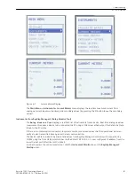
The
Instruments
menu shows measured or calculated values and some indications read from the 7SR5 device.
Measurement sub-menus display key quantities and information to aid with commissioning. The following
meters are available and are navigated around by using the ▲ and ▼ buttons dependent on the analogue
input configuration of the device.
The device instrumentation and metering provides real-time measured quantities and data. This is displayed
on the relay fascia LCD (when in the
Instruments
menu) or via the data communications interface.
6.2
Commissioning
6.2 Initial Startup
80
Reyrolle 7SR5, Operating, Manual
C53000-B7040-C013-1, Edition 05.2021
Summary of Contents for Reyrolle 7SR5
Page 6: ...6 Reyrolle 7SR5 Operating Manual C53000 B7040 C013 1 Edition 05 2021 ...
Page 10: ...10 Reyrolle 7SR5 Operating Manual C53000 B7040 C013 1 Edition 05 2021 ...
Page 40: ...40 Reyrolle 7SR5 Operating Manual C53000 B7040 C013 1 Edition 05 2021 ...
Page 76: ...76 Reyrolle 7SR5 Operating Manual C53000 B7040 C013 1 Edition 05 2021 ...
Page 114: ...114 Reyrolle 7SR5 Operating Manual C53000 B7040 C013 1 Edition 05 2021 ...

