10/11
Siemens
Temperature Controller RRV851
CE1N2725en
Building Technologies
27.08.2007
Y
1
1
Y
1
2
Y
1
4
Y
1
Y
2
Y4
Y
2
1
Y
2
2
Y
2
4
AC 24
/230V
N1
Y
1
1
Y
1
2
Y
1
4
Y
1
Y
2
Y4
Y
2
1
Y
2
2
Y
2
4
AC 24
/230V
N1
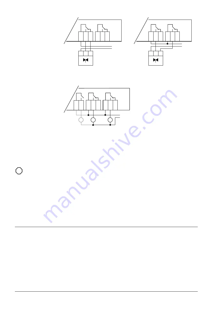
2-pipe FCU, 2-position control
(application A8)
Optional 3-position control (applications
A1, A2 and A8)
Y
1
1
Y
1
2
Y
1
4
Y
2
1
Y
2
2
Y
2
4
N1
Y
3
4
Y
3
1
CR2
CR1
RV
AC 24
/230V
Heat pumps (application A5)
(For single compressor heat pumps, CR2 is
not connected)
Note: Contact your local Siemens representative for application-specific wiring
diagrams and information.
•
External supply line fusing must be used.
•
All input and bus terminals are not protected against connection to AC 230 V.
•
Observe the technical data for fan relay outputs: Max. AC 250 V, 6(4) A.
•
All output cables used must satisfy insulation requirements with regard to
mains potential.
•
AC 24 V outputs must be segregated from AC 250 V outputs.
•
Care should be taken when cables pass through sharp metal openings,
conduits or ducts.
•
Double insulation on output cables is recommended.
•
Local installation regulations must be observed.
Product liability
The products may only be used in building services plant and applications as described
above. When using the products, all requirements specified under ”Technical data”
must be observed.
Output connections
Output connections
STOP
Note


