6/11
Siemens
Temperature Controller RRV851
CE1N2725en
Building Technologies
27.08.2007
Mounting and installation notes
The RRV851 controller can be mounted in any orientation using the following fixing
options:
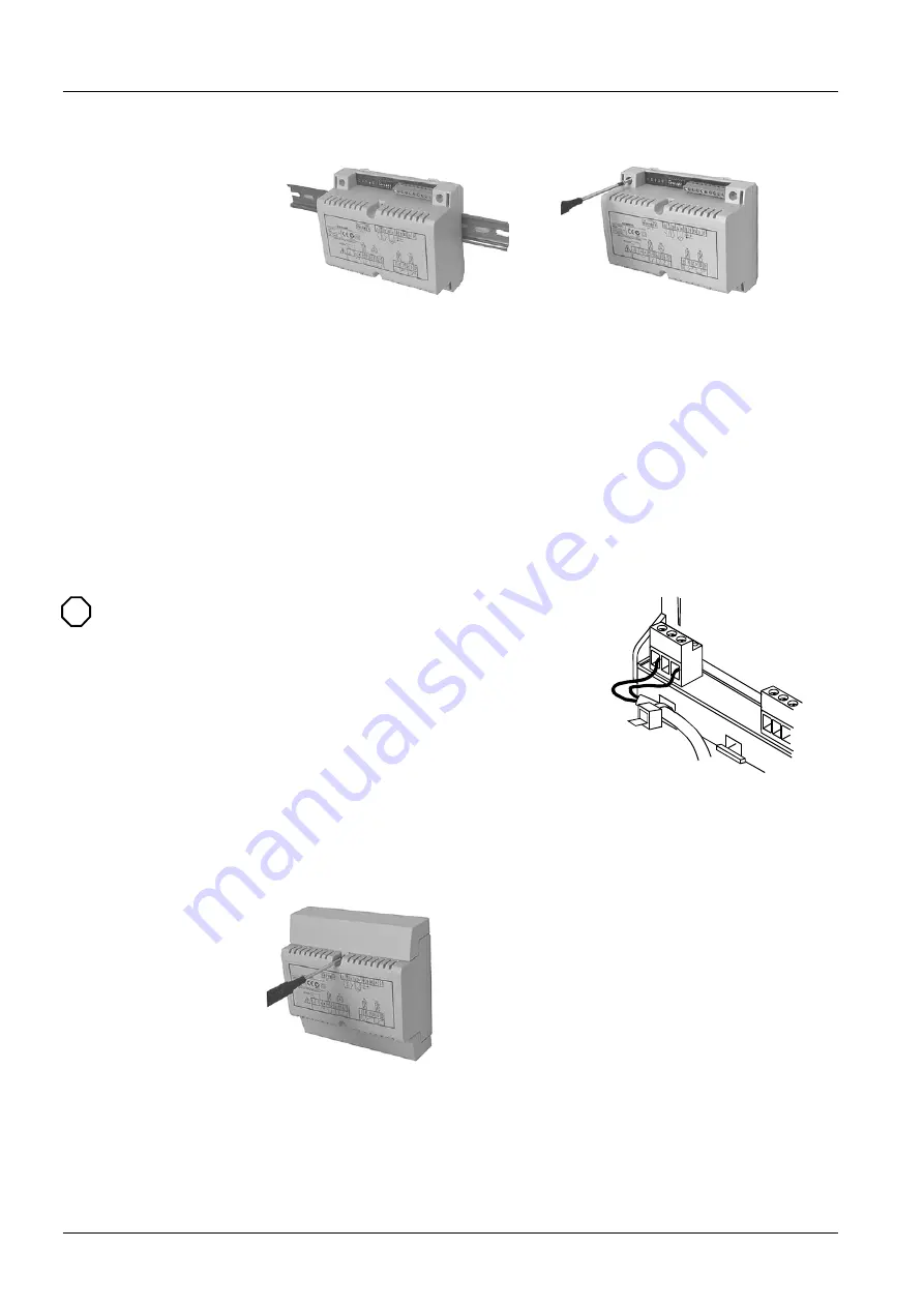
DIN rail mounting
The housing base is designed for snap-
mounting on DIN rails conforming to
EN 50022-35 × 7.5 (can be released
with a screwdriver).
Surface mounting
There are 2 drill holes for screw-mounting
(refer to “Dimensions”).
Screws: Max. diameter 3.5 mm, min. length
38 mm.
When mounting, note the following:
•
The controller should not be freely accessible after mounting
•
Ensure adequate air circulation to dissipate heat generated during operation
•
Easy access is required for service personnel
•
Local installation regulations must be observed
The Mounting Instructions are included in the RRV851 controller packaging.
When not mounting within a panel, cable strain
reliefs
must
be used for all wiring to (AC 230 V)
terminals. The conductors must be secured with
cable ties (see diagram).
Cable strain reliefs should be used for all wiring
to avoid disconnection.
27
2
5Z0
2
Terminal covers are provided in the RRV851 packaging box. The covers include
screws for fixing to the controller and knockout holes for cable entry. Covers should
only be used where suitable access is restricted to authorized personnel and there is
protection from ambient conditions. The covers will provide IP30 protection when
surface-mounted on the wall or FCU.
Removing the terminal covers
STOP
Note!
Terminal covers


