


Chapter 1
Introduction
RUGGEDCOM i802
Installation Guide
2
Description
Rated for Reliability in Harsh Environments
• Immunity to EMI and heavy electrical surges
• Hazardous Location Certification: Class I, Division 2
• -20 to +60 °C (-4 to 140 °F) operating temperature (optional -40 to +85°C or -40 to 185 °F)
• Conformal coated printed circuit boards (optional)
• Die cast aluminum enclosure
Memory Options
• Removable microSD/microSDHC card
Power Supply
• Dual low-voltage DC inputs: 24 VDC (9-32 VDC)
• Compression fit connections
• CSA/UL 60950 safety approved to 85 °C (185 °F)
Section 1.2
Description
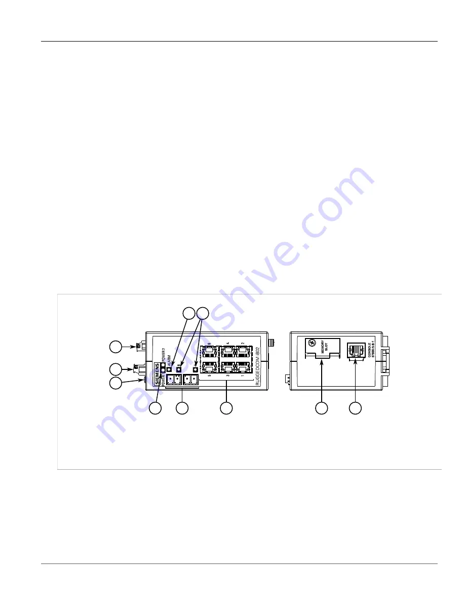
The RUGGEDCOM i802 features various ports, controls and indicator LEDs on the front panel for connecting,
configuring and troubleshooting the device.
4
9
10
8
2
1
3
5
6
7
Figure 1: RUGGEDCOM i802
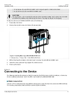
1.
Failsafe Alarm Relay
2.
Power Supply Terminal Block
3.
Chassis Ground Terminal
4.
POWER LEDs
5.
ALARM LED
6.
Port
Status LED
7.
Fiber Optic or Copper Gigabit Ethernet Ports
8.
Copper Ethernet Ports
9.
Access Plate
10.
RS-232 Console Port
(RJ-45)
•
Failsafe Alarm Relay
– Latches to default state when a power disruption or other alarm condition occurs. For
more information, refer to:
▪
Section 2.3, “Connecting the Failsafe Alarm Relay (If Equipped)”
▪
Section 4.3, “Failsafe Alarm Relay Specifications”
•
Power Supply Terminal Block
– A pluggable terminal block. For more information, refer to:
▪
Section 2.2, “Connecting Power”
Summary of Contents for RUGGEDCOM i802
Page 4: ...RUGGEDCOM i802 Installation Guide iv ...
Page 12: ...RUGGEDCOM i802 Installation Guide Chapter 1 Introduction Description 4 ...
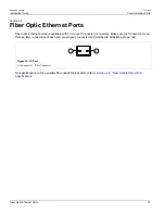
Page 22: ...RUGGEDCOM i802 Installation Guide Chapter 3 Communication Ports Fiber Optic Ethernet Ports 14 ...
Page 28: ...RUGGEDCOM i802 Installation Guide Chapter 5 Dimension Drawings 20 ...
Page 32: ...RUGGEDCOM i802 Installation Guide Chapter 6 Certification EMC and Environmental Type Tests 24 ...


