


Chapter 2
Installing the Device
RUGGEDCOM i802
Installation Guide
6
Connecting Power
1
1
2
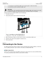
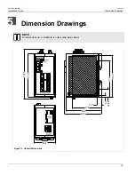
Figure 2: DIN Rail Mounting
1.
DIN Rail
2.
DIN Rail Bracket
2. Pull the release on the bracket down and slide the device onto the DIN rail. Let go of the release to lock the
device in position.
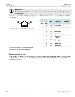
Section 2.2
Connecting Power
The RUGGEDCOM i802 supports a single low DC power supply with reverse polarity and dual independent
inputs. This allows for two redundant DC power sources with the same nominal voltage to be connected.
To connect power to the device, do the following:
IMPORTANT!
• Terminals P1-, P2- and GND are connected together internally. As such, if redundant power supplies
are connected, their negative terminals must be at the same potential.
• Do not field wire the DC power supply on the DC mains or Battery mains.
• Use only #16 gage wiring when connecting terminal blocks.
• Equipment must be installed according to applicable local wiring codes and standards.
1. Connect the positive wire from the power source to the positive terminal (P1+ or P2+) on the terminal block.
Summary of Contents for RUGGEDCOM i802
Page 4: ...RUGGEDCOM i802 Installation Guide iv ...
Page 12: ...RUGGEDCOM i802 Installation Guide Chapter 1 Introduction Description 4 ...
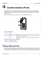
Page 22: ...RUGGEDCOM i802 Installation Guide Chapter 3 Communication Ports Fiber Optic Ethernet Ports 14 ...
Page 28: ...RUGGEDCOM i802 Installation Guide Chapter 5 Dimension Drawings 20 ...
Page 32: ...RUGGEDCOM i802 Installation Guide Chapter 6 Certification EMC and Environmental Type Tests 24 ...


