


RUGGEDCOM i802
Installation Guide
Chapter 2
Installing the Device
Connecting Power
7
1
2
3
4
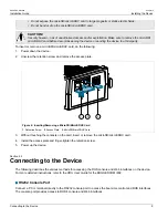
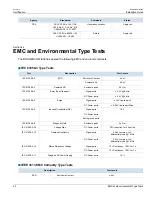
Figure 3: Terminal Block Wiring – Single DC Power Supply Input
1.
Positive Terminal
2.
Negative Terminal
3.
GND Terminal
4.
Chassis Ground Terminal
2. Connect the negative wire from the power source to the negative terminal (P1- or P2-) on the terminal block.
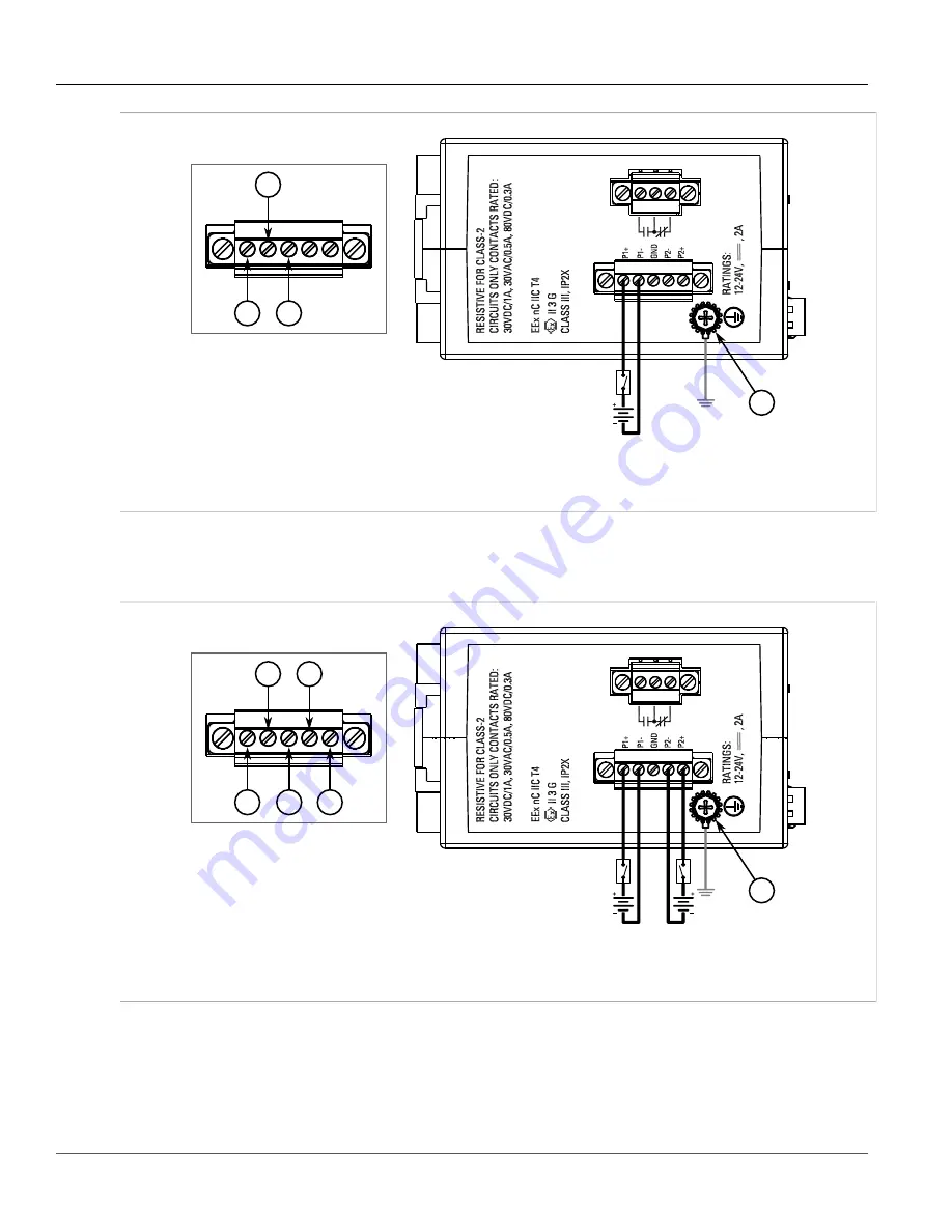
3. [Optional] If connecting a second redundant power source, repeat
Step 1
and
Step 2
, making sure to connect
the power supply to the P2 ports.
1
2
1
2
3
4
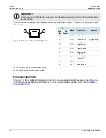
Figure 4: Terminal Block Wiring – Dual DC Power Supply Inputs
1.
Positive Terminal
2.
Negative Terminal
3.
GND Terminal
4.
Chassis Ground Terminal
4. Connect the chassis ground terminal to protective Earth.
Summary of Contents for RUGGEDCOM i802
Page 4: ...RUGGEDCOM i802 Installation Guide iv ...
Page 12: ...RUGGEDCOM i802 Installation Guide Chapter 1 Introduction Description 4 ...
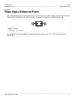
Page 22: ...RUGGEDCOM i802 Installation Guide Chapter 3 Communication Ports Fiber Optic Ethernet Ports 14 ...
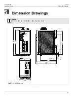
Page 28: ...RUGGEDCOM i802 Installation Guide Chapter 5 Dimension Drawings 20 ...
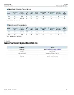
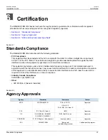
Page 32: ...RUGGEDCOM i802 Installation Guide Chapter 6 Certification EMC and Environmental Type Tests 24 ...


