


Chapter 3
Communication Ports
RUGGEDCOM i802
Installation Guide
12
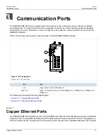
Copper Ethernet Ports
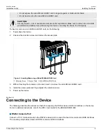
WARNING!
Electric shock hazard – risk of serious personal injury and/or equipment interference. If shielded
cables are used, make sure the shielded cables do not form a ground loop via the shield wire and the
RJ45 receptacles at either end. Ground loops can cause excessive noise and interference, but more
importantly, create a potential shock hazard that can result in serious injury.
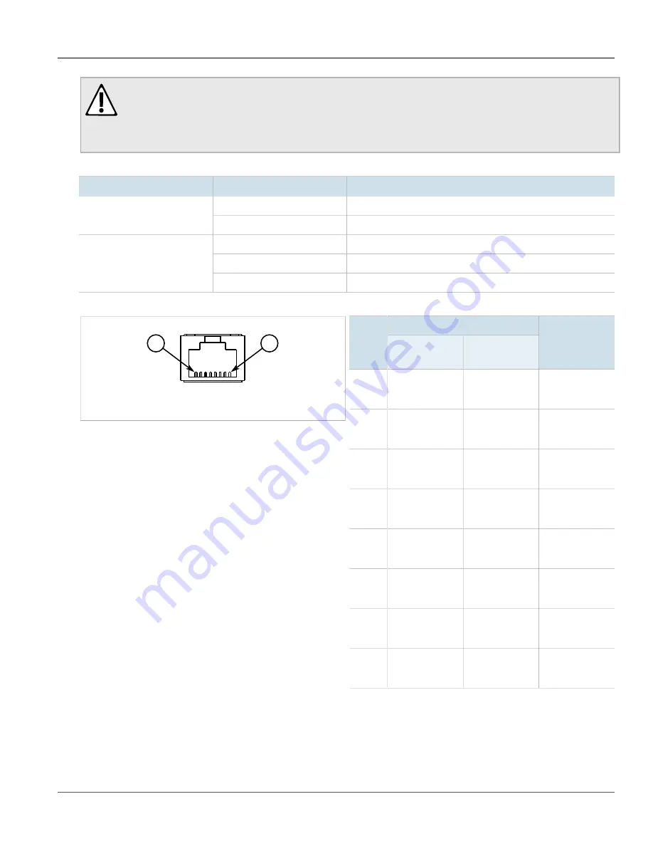
Each port features a
Speed
and
Link
LED that indicates the state of the port.
LED
State
Description
Yellow
The port is operating at maximum speed
Speed
Off
The port is not operating at maximum speed
Yellow (Solid)
Link established
Yellow (Blinking)
Link activity
Link
Off
No link detected
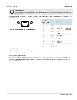
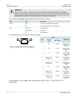
The following is the pin-out for the RJ45 male connectors:
1
8
Figure 9: RJ45 Ethernet Port Pin Configuration
Name
Pin
10/100TX
100FX
1000TX/SX/LX
Description
1
RX+
BI_DA+
Receive Data+
or Bi-Directional
Pair A+
2
RX-
BI_DA-
Receive Data-
or Bi-Directional
Pair A-
3
TX+
BI_DB+
Transmit Data+
or Bi-Directional
Pair B+
4
Reserved (Do
Not Connect)
BI_DC+
Transmit Data+
or Bi-Directional
Pair C+
5
Reserved (Do
Not Connect)
BI_DC-
Receive Data-
or Bi-Directional
Pair C-
6
TX-
BI_DB-
Transmit Data-
or Bi-Directional
Pair B-
7
Reserved (Do
Not Connect)
BI_DD+
Receive Data-
or Bi-Directional
Pair D+
8
Reserved (Do
Not Connect)
BI_DD-
Receive Data-
or Bi-Directional
Pair D-
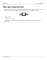
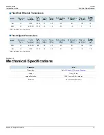
For specifications on the available copper Ethernet ports, refer to
Section 4.4, “Copper Ethernet Port
Specifications”
.
Summary of Contents for RUGGEDCOM i802
Page 4: ...RUGGEDCOM i802 Installation Guide iv ...
Page 12: ...RUGGEDCOM i802 Installation Guide Chapter 1 Introduction Description 4 ...
Page 22: ...RUGGEDCOM i802 Installation Guide Chapter 3 Communication Ports Fiber Optic Ethernet Ports 14 ...
Page 28: ...RUGGEDCOM i802 Installation Guide Chapter 5 Dimension Drawings 20 ...
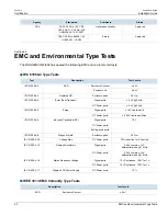
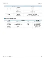
Page 32: ...RUGGEDCOM i802 Installation Guide Chapter 6 Certification EMC and Environmental Type Tests 24 ...


