Chapter 2
Installing the Device
RUGGEDCOM RUGGEDCOM RS940G
Installation Guide
12
Cabling Recommendations
IMPORTANT!
The serial console port is intended to be used only as temporary connections during initial
configuration or troubleshooting.
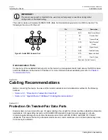
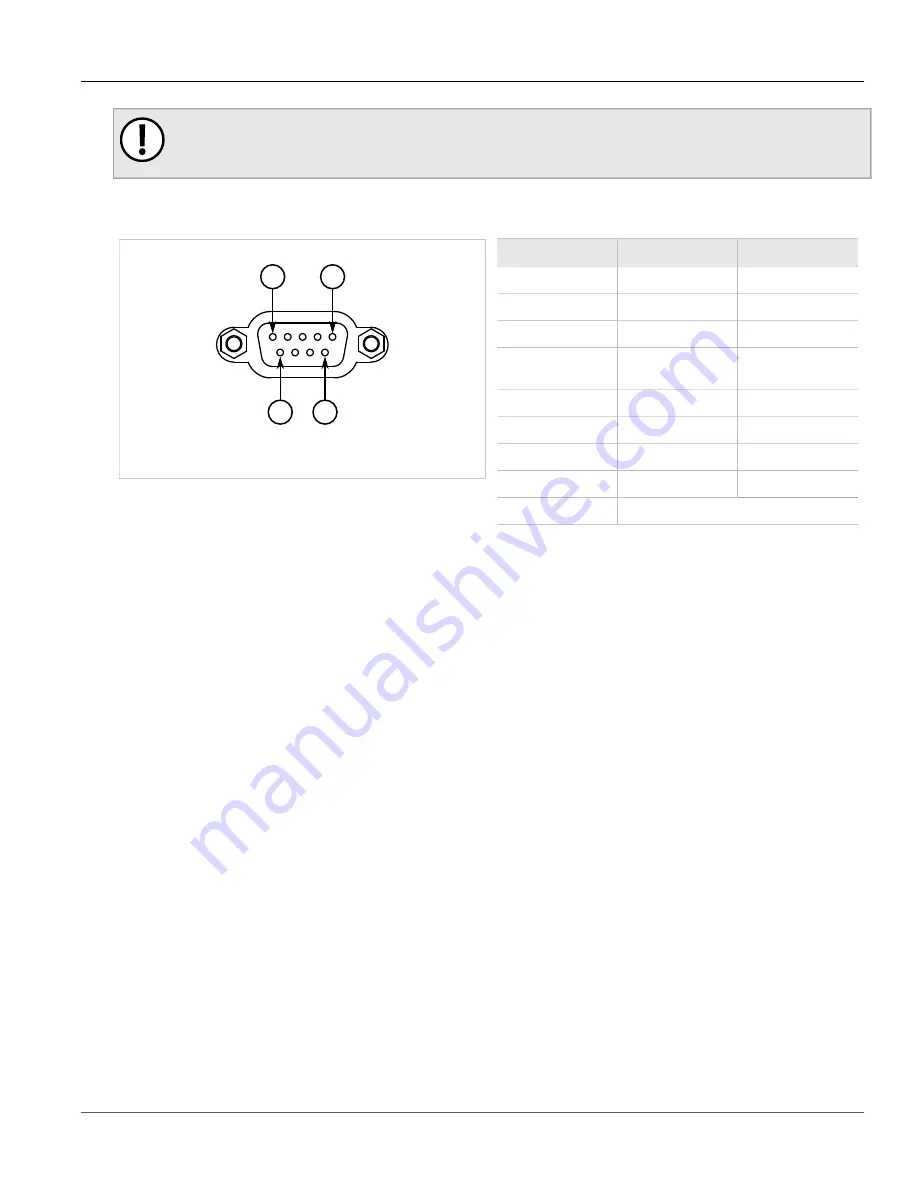
The serial console port implements RS232 DCE (Data Communication Equipment) on a DB9 connector. The
following is the pin-out for the port:
5
9
6
1
Figure 8: Serial DB9 Console Port
Pin
Name
Description
1
DCD
Data Carrier Detect
2
RX
Receive Data
3
TX
Transmit Data
4
DTR
Data Terminal
Ready
5
GND
Signal Ground
6
DSR
Data Set Ready
7
RTS
Request to Send
8
CTS
Clear To Send
9
Reserved (Do Not Connect)
Communication Ports
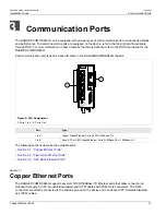
Connect any of the available Ethernet ports on the device to a management switch and access the ROS console
and Web interfaces via the device's IP address. For more information about available ports, refer to
Chapter 3,
Communication Ports
.
Section 2.5
Cabling Recommendations
Before connecting the device, be aware of the recommendations and considerations outlined in the following
sections:
•
Section 2.5.1, “Protection On Twisted-Pair Data Ports”
•
Section 2.5.2, “Gigabit Ethernet 1000Base-TX Cabling Recommendations”
Section 2.5.1
Protection On Twisted-Pair Data Ports
Siemens does not recommend the use of copper cabling of any length for critical, real-time substation automation
applications. All copper Ethernet ports on RUGGEDCOM products include transient suppression circuitry
to protect against damage from electrical transients and conform with IEC 61850-3 and IEEE 1613 Class 1
standards. This means that during a transient electrical event, communications errors or interruptions may occur,
but recovery is automatic.

