Chapter 3
Communication Ports
RUGGEDCOM RX1000
Installation Guide
24
Pulse-Per-Second (PPS) Output
1
2
3
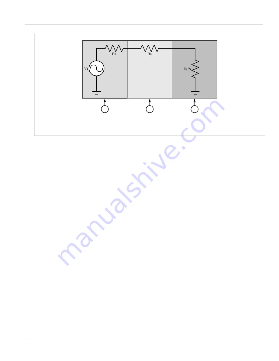
Figure 24: IRIG-B Simplified Schematic
1.
Source
2.
Cabling
3.
Device
The maximum number of devices (N) that can be connected to the source is determined by checking if the source
current (IS) required to drive the connected devices is less than the maximum drive current the source can
provide, and verifying that the load voltage (VL) the connected devices see is greater than the minimum required
voltage.
For specifications for the IRIG-B outputs, refer to
Section 4.5, “IRIG-B Output Specifications”
.
Section 3.7.2
Pulse-Per-Second (PPS) Output
The PTP card supports one Pulse-Per-Second (PPS) output. When enabled through ROX, the card outputs a 5 V
pulse every second.
Section 3.7.3
GPS Antenna Installation Recommendations
The signals received from the GPS satellite network are at a frequency of 1575.42 MHz with a minimum power
of -162 dBW. The GPS antenna must have a clear view of the sky in order to receive the low power signals and
track the maximum number of satellites. Rooftops or other structures clear of obstructions and with a clear view
of the horizon are ideal.
Elements of a typical GPS antenna system include:
• Active GPS Antenna (required)
• Coaxial cable to connect the elements (required)
• Lightning arrestor (optional)
• Line Amplifier or Filter (optional)
To establish proper GPS signal reception, the overall system of antenna, cabling, lightning arrestor, line amplifier
and filters requires a relative gain which should be greater than 5 dBi but less than 18 dBi (to avoid signal
saturation at the receiver input).


