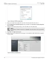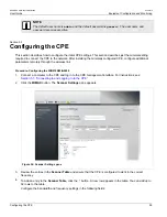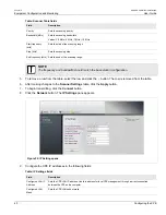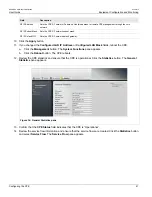
RUGGEDCOM WiN5100/WiN5200
User Guide
Chapter 4
Installation Procedure
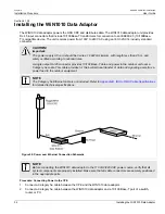
Connecting the Ground Cable
27
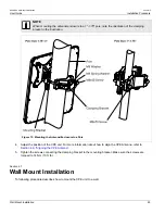
8. Tighten the screws connecting the arm bracket to the CPE unit and mounting bracket. Make sure the screws
are torqued to 24 Nm (17.7 ft. lb.).
Section 4.8
Connecting the Ground Cable
When connecting the ground cable to the device, make sure to use a 10 AWG grounding cable and torque the
screw to 15 Nm (11 ft. lb.).
Section 4.9
Aligning the CPE Antenna
NOTE
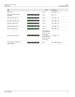
For information on the location of and how to read the RSSI LED indicators, see
.
Procedure: Aligning the CPE Antenna
1. Point the antenna towards the general direction of the base station.
2. Verify that power is applied to the CPE. The PWR LED should be ON.
3. Verify that at least one green RSSI LED is ON, indicating that the CPE is synchronized with the base station.
If the CPE is not synchronized with the base station, ensure that all parameters are configured properly. If
the CPE is still not synchronized with the base station, improve link quality by changing the direction of the
antenna or by placing the CPE at a higher or alternate location.
4. Rotate the CPE until the maximum RSSI link quality reading is achieved. If you encounter prolonged difficulty
in achieving the expected link quality, try to improve the reception quality by placing the CPE at a higher point
or in an alternate location.
NOTE
Ensure that the front of the antenna is always facing the base station. In some conditions, such
as when the line of sight to the base station is impeded, better reception may be achieved using a
reflected signal. In this case, direct the antenna towards the reflecting object, rather than towards
the base station.
In some cases, the antenna may need to be tilted to ensure that the level at which the CPE
receives transmissions from the base station (and vice versa) is not too high. When only the last
RSSI LED is on, this indicates saturation and that the received signal level is too high. This must
be avoided, preferably by tilting the antenna upwards. As a rule of thumb, if the CPE is located
at a distance of less than 300 meters from the base station, it is recommended to tilt the antenna
upwards by approximately 10° to 15°.
Summary of Contents for RUGGEDCOM WiN5100
Page 2: ...RUGGEDCOM WiN5100 WiN5200 User Guide ii ...
Page 8: ...RUGGEDCOM WiN5100 WiN5200 User Guide FCC Statement And Cautions viii ...
Page 26: ...RUGGEDCOM WiN5100 WiN5200 User Guide Chapter 2 Product Description LED Indicators 18 ...
Page 28: ...RUGGEDCOM WiN5100 WiN5200 User Guide Chapter 3 Mounting Wall Mounting 20 ...
Page 106: ...RUGGEDCOM WiN5100 WiN5200 User Guide Appendix A WiN5100 WiN5200 Specifications 98 ...
Page 114: ...RUGGEDCOM WiN5100 WiN5200 User Guide Appendix D RUGGEDCOM CPE Warranty 106 ...


