RUGGEDCOM WiN5100/WiN5200
User Guide
Chapter 4
Installation Procedure
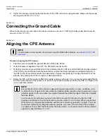
Assembling the RJ45 Connector
33
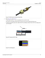
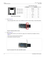
5. Refer to
• Loop the drain wire over the prepared grounding shield of the RJ45.
• Solder in position and trim off the remaining drain wire.
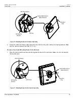
Figure 25: Solder the Drain Wire
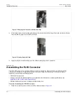
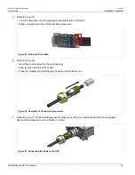
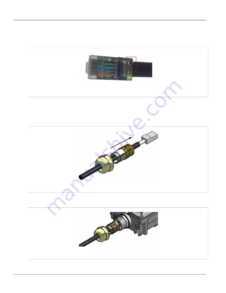
6. Refer to
• Insert the modular plug into the plug housing.
• Align the latch with the LATCH slot.
• Press the modular plug into the plug housing until it bottoms out.
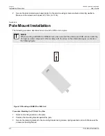
Figure 26: Assembly of Connector Components
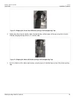
7. Refer to
. While maintaining inward pressure on the plug or keeping the dust cover engaged,
tighten the compression nut to 0.56Nm (5 In-lbs).
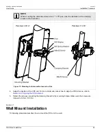
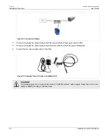
Figure 27: Connecting the Cable to the CPE
Summary of Contents for RUGGEDCOM WiN5100
Page 2: ...RUGGEDCOM WiN5100 WiN5200 User Guide ii ...
Page 8: ...RUGGEDCOM WiN5100 WiN5200 User Guide FCC Statement And Cautions viii ...
Page 26: ...RUGGEDCOM WiN5100 WiN5200 User Guide Chapter 2 Product Description LED Indicators 18 ...
Page 28: ...RUGGEDCOM WiN5100 WiN5200 User Guide Chapter 3 Mounting Wall Mounting 20 ...
Page 106: ...RUGGEDCOM WiN5100 WiN5200 User Guide Appendix A WiN5100 WiN5200 Specifications 98 ...
Page 114: ...RUGGEDCOM WiN5100 WiN5200 User Guide Appendix D RUGGEDCOM CPE Warranty 106 ...

