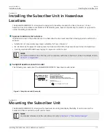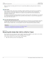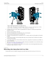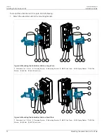
RUGGEDCOM WIN5151
Installation Guide
Chapter 2
Installing the Subscriber Unit
Connecting to a RUGGEDCOM RP100 or RP110
19
1. Connect an indoor-to-outdoor CAT-5e cable to the Ethernet port on the injector. For information on cable
requirements, refer to
Section 4.6, “IDU to ODU Cable Specifications”
.
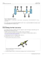
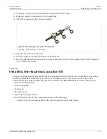
2. Apply the PoE connector kit to the other end of the CAT-5e cable. For more information, refer to
Section 2.8.4, “Assembling the PoE Connector”
3. Connect the modified end of the cable to the
DC/ETH
port on the subscriber unit.
1
3
4
4
2
7
6
5
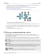
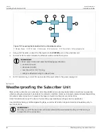
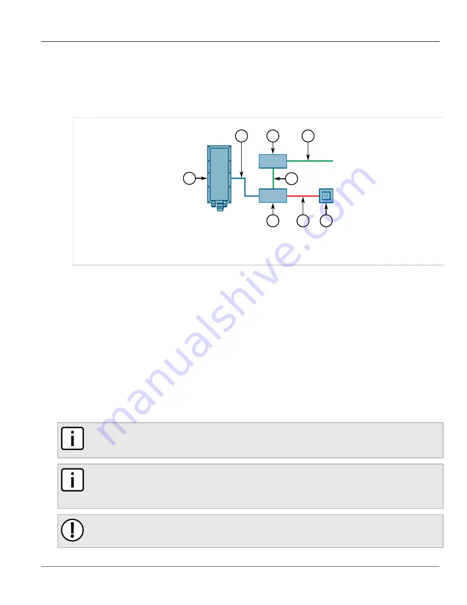
Figure 9: Connecting the RUGGEDCOM WIN1010 PoE Injector
1.
Subscriber Unit
2.
PoE Cable
3.
Switch or Router
4.
Ethernet
5.
RUGGEDCOM WIN1010
6.
AC Power Cable
7.
AC Power
4. Connect a CAT-5e cable between the RUGGEDCOM WIN1010 and a 10/100Base-T port of a switch or router.
5. Make sure all system components are properly installed and all cable connectors are securely positioned in
the appropriate ports.
6. Connect the data adapter to the 110/220 VAC mains.
Section 2.8.3
Connecting to a RUGGEDCOM RP100 or RP110
The RUGGEDCOM RP100 and RP110 are optional power injectors for powering and providing data to the
RUGGEDCOM WIN5151. The RUGGEDCOM RP100 and RP110 meet a wider temperature and voltage range than
the standardRUGGEDCOM WIN1010.
When the subscriber unit is connected to a RUGGEDCOM RP100 or RP110, make sure there is a solid connection
between the lightning protector and the subscriber unit. The following illustration details a typical installation.
NOTE
A shielded cable must be used and connected to local ground at both the subscriber unit and lightning
protector.
NOTE
The lightning protector must meet the necessary requirements of IEC/UL/CSA 60950-1. The clamping
voltage must also be less than 60 V and the protector must not activate when the voltage is less than
56 V. For more information about these requirements, contact Siemens Customer Support.
IMPORTANT!
Install the lightning protector and the RUGGEDCOM RP100/RP110 as close as possible.


