RUGGEDCOM WIN5151
Installation Guide
Chapter 1
Introduction
Description
3
W.LINK
RSSI
PWR
ANT 2
ANT 1
W.LINK
ETH/PWR
RSSI
PWR
6
1
2
7
4
3
5
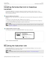
Figure 1: RUGGEDCOM WIN5151 (AC Model)
1.
ANT 1 Port
2.
ETH/PWR Port
3.
RSSI LEDs
4.
W.LINK LED
5.
PWR LED
6.
ANT 2 Port
7.
Chassis Ground
RSSI
W.LINK PWR
12VDC
ANT 1
ANT 2
ETH/PWR
RSSI
W.LINK PWR
7
2
1
8
3
5
4
6
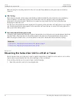
Figure 2: RUGGEDCOM WIN5151 (DC Model)
1.
12VDC Port
2.
ANT 1 Port
3.
ETH/PWR Port
4.
RSSI LEDs
5.
W.LINK LED
6.
PWR LED
7.
ANT 2 Port
8.
Chassis Ground
ANT 1 and ANT 2 Ports
Ports for connecting primary and secondary external antennas. For information about
connecting the antennas, refer to
Section 2.6, “Installing the Antennas”
.
RSSI LEDs
Indicates the received signal strength.
LED
RSSI Level
< -90
-85 to -90
-80 to -85
-75 to -80
-70 to -75
-65 to -70
-20 to -60
> -20
W.LINK LED
Indicates when the subscriber unit is connected with a base station.


