background image

RUGGEDCOM WIN

User Guide

Chapter 3

Device Management

Copying Files to the Secondary Bank

31

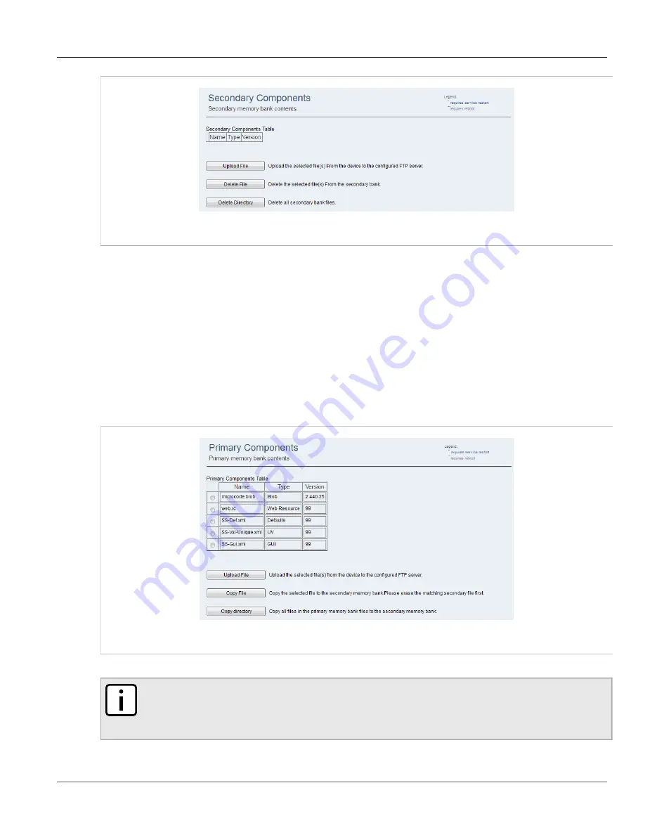
Figure 24: Secondary Components Screen

2. Select a file from the table.
3. Click 

Upload File

.

4. View the status of the operation. For more information, refer to 

 Section 3.4.8, “Viewing the Status of an

Operation” 

.

Section 3.4.7.3

Copying Files to the Secondary Bank

To copy files to the secondary bank, do the following:
1. Navigate to 

Management » SW Upgrade » Primary Bank

. The 

Primary Components

 screen appears.

Figure 25: Primary Components Screen

2. Select a file from the table.

NOTE

Before copying the file, make sure it does not already exist in the Secondary memory bank. If the

file is present in the Secondary memory bank, delete the file from the Secondary memory bank

before copying. For more information, refer to 

 Section 3.4.7.4, “Deleting Memory Bank Files” 

.

Summary of Contents for RUGGEDCOM WIN5151

Page 1: ...WIN5137 V WIN5137 V GPS WIN5149 WIN5151 WIN5151 V WIN5151 V GPS WIN5158 WIN5158 V WIN5214 WIN5218 WIN5223 WIN5225 WIN5235 WIN5237 WIN5249 WIN5251 WIN5258 02 2017 RC1308 EN 02 Preface Introduction 1 Using WIN v5 0 2 Device Management 3 System Administration 4 Setup and Configuration 5 ...

Page 2: ...anual might be trademarks whose use by third parties for their own purposes would infringe the rights of the owner Security Information Siemens provides products and solutions with industrial security functions that support the secure operation of plants machines equipment and or networks They are important components in a holistic industrial security concept With this in mind Siemens products and...

Page 3: ...ion Duplexing TDD 5 1 4 Coding Rates 5 1 5 Modulation 5 1 6 Convolution Turbo Coding Correction 5 1 7 Deployment Models 5 1 7 1 PTP Deployment 6 1 7 2 PMP Deployment 6 1 7 3 Non Line of Sight 6 1 7 4 Channelization 6 1 8 Service Flows 6 1 8 1 Service Flow Classification 7 1 8 2 Default Service Flows 7 1 8 3 Scheduling 7 Chapter 2 Using WIN v5 0 9 2 1 Configuring Network Parameters in Windows 9 2 2...

Page 4: ...ding Software from an FTP Server 28 3 4 7 Managing Memory Banks 28 3 4 7 1 Viewing Memory Bank Files 29 3 4 7 2 Uploading Files to the FTP Server 30 3 4 7 3 Copying Files to the Secondary Bank 31 3 4 7 4 Deleting Memory Bank Files 32 3 4 8 Viewing the Status of an Operation 32 3 4 9 Canceling an Operation 33 Chapter 4 System Administration 35 4 1 Configuring the Device Name 35 4 2 Managing Links 3...

Page 5: ...ng Allowed Base Stations 58 5 3 2 Adding Base Station Identifiers 59 5 3 3 Deleting Base Station Identifiers 60 5 3 4 Connecting to Specific Base Stations 61 5 3 5 Disconnecting from Specific Base Stations 62 5 3 6 Connecting to Allowed Operator ID 63 5 4 Enabling Disabling the GPS 64 5 5 Configuring Neighbor Scanning 65 5 6 Enabling Disabling Fast Network Entry 66 5 7 Configuring Scan Duration 67...

Page 6: ...C Address Table 85 5 17 2 Configuring the MAC Address Table 86 5 17 3 Clearing the MAC Address Table 87 5 17 4 Enabling Disabling Mini Jumbo Frames 88 5 17 5 Configuring the Access List 88 5 17 6 Adding Entries to the Access List 90 5 17 7 Deleting Entries from the Access List 90 5 18 Configuring the WiMAX Radio 91 5 19 Managing WiMAX Authentication 93 5 19 1 Viewing the Device Authentication Sett...

Page 7: ...lustrations of the management interface screens are presented for illustrative purposes and may appear with minor differences in a working system CONTENTS Alerts Related Documents System Requirements Training Customer Support Alerts The following types of alerts are used when necessary to highlight important information DANGER DANGER alerts describe imminently hazardous situations that if not avoi...

Page 8: ...mpatible Microsoft Internet Explorer 11 Google Chrome 31 or 32 Mozilla Firefox 25 or 26 Apple Safari 5 1 Opera 18 Training Siemens offers a wide range of educational services ranging from in house training of standard courses on networking Ethernet switches and routers to on site customized courses tailored to the customer s needs experience and application Siemens Educational Services team thrive...

Page 9: ...local hotline center to submit a Support Request SR To locate a local hotline center visit http www automation siemens com mcms aspa db en automation technology Pages default aspx Mobile App Install the Industry Online Support app by Siemens AG on any Android Apple iOS or Windows mobile device and be able to Access Siemens extensive library of support documentation including FAQs and manuals Submi...

Page 10: ...Preface RUGGEDCOM WIN User Guide x Customer Support ...

Page 11: ...and troubleshooting tools HTTPS SNMPv2 and SNMPv3 Management VLAN Remote software upgrades via SFTP Antenna alignment with LEDs Network Interface Protocol QoS according to IEEE 802 16e 2009 SSHv2 Password Management local and RADIUS Device Authentication via PKMv2 EAP TLS TTLS X 509 certificates NTP server Ethernet Lock feature MAC address list Device Features Mobile WiMAX Wave 2 MIMO Features Tim...

Page 12: ...le Make sure to take appropriate precautions when shipping the device beyond the boundaries of the trusted environment Replace the SSH and SSL keys with throwaway keys prior to shipping Take the existing SSH and SSL keys out of service When the device returns create and program new keys for the device Use a AAA server whenever possible When using SNMP Simple Network Management Protocol Limit the n...

Page 13: ...r Siemens products used in coordination with the device for further security recommendations Section 1 2 Mobile WiMAX Wave 2 MIMO Features Multiple Input Multiple Output MIMO describes systems that use more than one radio and antenna system at each end of the wireless link In the past it was too costly to incorporate multiple antennas and radios in a subscriber terminal Recent advances in radio mi...

Page 14: ...iMAX uses transmit diversity in the downlink direction to provide spatial diversity to enhance the signal quality to a specific subscriber located anywhere within the range of the antenna beam Although providing less signal gain than beam forming transmit diversity is more robust for mobile users as it does not require prior knowledge of the path characteristics of a subscriber s particular freque...

Page 15: ...n making it more resistant to potential over the air errors The coding rate is the ratio of user data to the total data transmitted including the redundant error correction data The base station supports coding rates of 1 2 2 3 and 3 4 Section 1 5 Modulation The modulation technique specifies how the data is coded within the OFDMA carriers The base station supports QPSK 16 Quadarature Amplitude Mo...

Page 16: ... link is considered non LOS if natural or man made structures block the visible path between the base station and the subscriber In this case a wireless link can be established only if a reflective path can be established between the base station and subscriber Section 1 7 4 Channelization The SS is a frequency specific system with the frequency band defined by the PHY unit The use of the operatin...

Page 17: ...el with predictable transmission characteristics By analyzing the total of all requests from all subscribers the base station ensures that uplink and downlink traffic conforms to the current service level agreements SLAs Centralized scheduling increases predictability of traffic eliminates contention and provides the maximum opportunity for reducing overhead A regular period is scheduled for subsc...

Page 18: ...raffic based on unused bandwidth after all higher level traffic scheduling requirements are serviced Typical applications include Internet access and email Best effort service flows can be assigned a priority of 0 to 7 Unsolicited Grant Service UGS The base station schedules a continuous series of transmit opportunities for the subscriber to send fixed size data packets This schedule supports real...

Page 19: ...eters for other operating systems refer to the user documentation for that operating system The device can be pre configured in the lab eliminating the need for configuration in the field After installing a pre configured device configure additional parameters remotely through the wireless link NOTE The following procedure describes how to configure the parameters using Microsoft Windows 7 To conf...

Page 20: ...ection Status Dialog Box 6 Click Local Area Connection The Local Area Connections Properties dialog box appears with the General tab selected Figure 3 Windows Local Area Connection Properties Dialog Box 7 In the Items list select Internet Protocol TCP IP and then click Properties The Internet Protocol TCP IP Properties dialog box appears ...

Page 21: ...tion Status dialog box click Close 12 Log in to the device to test the network settings For more information refer to Section 2 2 Logging In Section 2 2 Logging In To log in to the device do the following 1 Launch a web browser and type https 192 168 254 251 in the address parameter NOTE For information on browser versions and compatibility refer to System Requirements 2 Press Enter The browser s ...

Page 22: ...ssword box type a password NOTE For instructions on how to navigate the management interface refer to Section 2 4 Using the Web based User Interface 6 Click OK The RUGGEDCOM WIN management interface appears Figure 6 RUGGEDCOM WIN Management Interface 7 Optional If logging in for the first time set the operating mode and initial configuration Section 2 3 Logging Out To log out do the following 1 Na...

Page 23: ... device s management interface through the device s LAN or RF IP address The management interface consists of three main areas Configuration Buttons a set of buttons providing access to configuration options To select a group of configuration options click a button Options Pane a set of links providing access to individual configuration panes To select a specific configuration pane click a link Di...

Page 24: ...debugging the device It is intended primarily for use by RUGGEDCOM WIN Customer Support To access developer mode do the following NOTE Developer mode is only available to developers for advanced troubleshooting purposes Developers cannot access the device without logging into the system first IMPORTANT The developer mode password is provided by Siemens To obtain password contact Siemens Custom Sup...

Page 25: ...0 Accessing Developer Mode 15 Figure 9 Developer Mode Screen 2 In the Password box type the password for developer mode The status of the password appears in the Status box If the password is correct the message Correct Password appears 3 Click Apply ...

Page 26: ...Chapter 2 Using WIN v5 0 RUGGEDCOM WIN User Guide 16 Accessing Developer Mode ...

Page 27: ... Section 3 4 Managing Software Versions and Upgrades Section 3 1 Configuring Syslog To configure the syslog do the following 1 Navigate to Management Log Management The Syslog screen appears Figure 10 Syslog Screen 2 Configure the following parameter s as required Parameter Description Syslog Enable Synopsis Enable Disable Default Disable Enables or disables logging Server IP Synopsis IPv4 address...

Page 28: ... Statistics Device Info The Device Info screen appears Figure 11 Device Info Screen The table provides the following information Parameter Description Serial Number Displays the device s serial number Calibration Version Displays the device s calibration version RF ID Displays the device s radio frequency identification number HW ID Displays the devices s hardware identification number Section 3 3...

Page 29: ...Name MS ID Displays the mobile station MAC address CPE Status Synopsis Init DL Synchronization Handover DL acquisition UL Acquisition Ranging Handover ranging Capabilities negotiation Authorization Registration DHCP TOD TFTP Operational Sleep IDLE Aborted Displays the device s current status Link Up Time Displays the time since the device became operational Up Time Displays the time since the last...

Page 30: ...ion Authorization Registration DHCP TOD TFTP Operational Sleep IDLE Aborted Displays the current SS status DL RSSI Displays the downlink received signal strength in dBm DL CINR Displays the downlink carrier to interference and noise ratio in dB DL CINR R3 Displays Displays R3 downlink carrier to interference and noise ratio in dB MIMO mode Synopsis SISO MIMO A MIMO B Displays the SS Multiple Input...

Page 31: ...second 3 To clear the RF Statistics click Clear statistics Section 3 3 3 Viewing and Clearing Network Statistics To view LAN and RF network information and statistics and clear the network statistics do the following 1 Navigate to Statistics Network The Network screen appears Figure 14 Network Screen 2 View the LAN and RF network information Parameter Description Current LAN IP Address Displays th...

Page 32: ...ervice flows do the following 1 Navigate to Statistics Service Flow The Service Flow screen appears Figure 15 Service Flow Screen 2 View the service flow statistics in the Service flow statistics table Parameter Description SF Name Displays the name of the service flow Service flow ID Displays a numeric identifier for the service flow CID Displays the connection identifier for the service flow Dir...

Page 33: ...ystem software can be stored on the device one in each memory bank Each memory bank is designated as either the Primary or Secondary memory bank When you reset or reboot the device it always runs the software installed in the Primary bank The Web console provides controls to change the Primary and Secondary designations on the memory banks and to reboot the device using the Secondary memory bank f...

Page 34: ...en click Run Secondary The device will reset and load the software image in the secondary memory bank This process will take approximately two minutes 6 Commit the new software image as the new default software Again on the SW Properties screen click Set As Primary in order to set the current memory bank currently denoted Secondary as Primary Doing so will cause the software in the memory bank new...

Page 35: ...umber of the memory bank selected as the Secondary memory bank Secondary CDC Displays the filename of the CDC Customer Defaults Configuration file in the Secondary memory bank Secondary UV Displays the filename of the UV Unique Value configuration file in the Primary memory bank Configuration Changes Counter Displays the number of changes made to configuration values on the device This value only ...

Page 36: ...ots and runs the Primary software image Section 3 4 4 Loading the Secondary Software Version To load the Secondary software image into the memory bank do the following NOTE Before performing this procedure make sure the version in the Current Active Bank parameter is displayed as Primary 1 Navigate to Management SW Upgrade The SW Properties screen appears ...

Page 37: ...and runs the Secondary software image Section 3 4 5 Configuring the Primary Software Version To configure the currently running software image as the Primary software image and switch the designation from being the Secondary image do the following 1 Navigate to Management SW Upgrade The SW Properties screen appears Figure 19 SW Properties Screen 2 Click Set as Primary ...

Page 38: ...le to download Package The software package file provided with an upgrade package For example ruggedupgrade ini VxWorks An operating system file For example vxWorks44462418 Z Web Resource A web console template file For example web rc CDC A Common Default Configuration file For example BS Val Cdc xml UV A Unique Value file For example BS Val Unique xml File Name The name of the file you want to do...

Page 39: ...g Memory Bank Files To view files in the Primary memory bank do the following To view the Primary memory bank files navigate to Management SW Upgrade Primary Bank The Primary Components screen appears Figure 21 Primary Components Screen Or To view the Secondary memory bank files navigate to Management SW Upgrade Secondary Bank The Secondary Components screen appears Figure 22 Secondary Components ...

Page 40: ...rmation for the files in the memory bank upload files from the memory bank to your FTP server and delete files from the memory bank Before uploading files to an FTP server you must configure an FTP server on the FTP Server Properties screen For more information about how to configure the FTP server properties refer to Section 3 4 6 Downloading Software from an FTP Server To upload a file to the FT...

Page 41: ...ng Files to the Secondary Bank To copy files to the secondary bank do the following 1 Navigate to Management SW Upgrade Primary Bank The Primary Components screen appears Figure 25 Primary Components Screen 2 Select a file from the table NOTE Before copying the file make sure it does not already exist in the Secondary memory bank If the file is present in the Secondary memory bank delete the file ...

Page 42: ...bank first For more information refer to Section 3 4 7 3 Copying Files to the Secondary Bank 1 Navigate to Management SW Upgrade Secondary Bank The Secondary Components screen appears Figure 26 Secondary Components Screen 2 Select a file from the table 3 To delete a file click Delete File Or To delete all files click Delete Directory 4 View the status of the operation For more information refer to...

Page 43: ...rovides the following information Parameter Description Index Displays a unique identifier for the file Operation Synopsis Download Upload Delete Copy Operations indicates the completion of a batch operation on several files Displays the file transfer operation performed on the file File Name Displays the file name for the uploaded or downloaded file Status Synopsis OK Not Started In Process Failu...

Page 44: ...Chapter 3 Device Management RUGGEDCOM WIN User Guide 34 Canceling an Operation Figure 28 File Transfer Status Screen 2 Click Cancel ...

Page 45: ...s Section 4 5 Rebooting the Device Section 4 6 Restoring Factory Defaults Section 4 7 Managing Users Section 4 8 Enabling Disabling SSH Shell Access Section 4 9 Managing Keys and Certificates Section 4 10 Managing Alarms Section 4 11 Configuring the NTP Server Section 4 12 Locking the Device Section 4 13 Configuring RADIUS User Authentication Section 4 1 Configuring the Device Name To configure th...

Page 46: ...en Section 4 2 Managing Links This section describes how to configure Link WatchDog and Link Timeout CONTENTS Section 4 2 1 Configuring Link WatchDog Section 4 2 2 Configuring Link Timeout Section 4 2 1 Configuring Link WatchDog Link WatchDog resets the device if it is not in an operational state for a continuous time To configure Link WatchDog do the following 1 Navigate to Management System Func...

Page 47: ...the WatchDog timer will start again from zero When the device s channel scanner is empty WatchDog will not reset the device Always the device always resets after the configured timeout expires when no RF link has been established 3 Click Apply Section 4 2 2 Configuring Link Timeout Link Timeout min is used to configure the number of minutes during which Link WatchDog will try to reset the device b...

Page 48: ...value is 15 3 Click Apply Section 4 3 Changing the Administrator Password To change an administrator password do the following 1 Navigate to Management Access Permissions The Device Access Permissions screen appears Figure 32 Device Access Permissions Screen 2 In the Password parameter type the new password The default password is generic 3 In the Retype Password parameter retype the new password ...

Page 49: ...ified via RUGGEDCOM NMS do the following 1 Navigate to Management Access Permissions The Device Access Permissions screen appears 1 2 Figure 33 Device Access Permissions Screen 2 In the Login retries before Trap list select the maximum number of failed login attempts allowed by the device 3 Click Apply Section 4 5 Rebooting the Device To reboot the device do the following 1 Navigate to Management ...

Page 50: ...ng Factory Defaults To restore factory defaults do the following 1 Navigate to Management System Functions The System Functions screen appears Figure 35 System Functions Screen 2 Click Set factory defaults to restore all the factory defaults or click Set partial defaults to restore the factory defaults except for parameters that affect device connectivity ...

Page 51: ...ite options including user definitions Guest users can access all read options only CONTENTS Section 4 7 1 Adding Users Section 4 7 2 Deleting Users Section 4 7 1 Adding Users To add a user profile do the following NOTE Only users with Admin access rights can manage user profiles 1 Navigate to Management Access Permissions The Device Access Permissions screen appears 1 2 Figure 36 Device Access Pe...

Page 52: ... a user profile do the following NOTE Only users with Admin access rights can manage user profiles 1 Navigate to Management Access Permissions The Device Access Permissions screen appears 1 2 Figure 37 Device Access Permissions Screen 1 Add 2 Delete 2 Select a user from the Permitted Users list 3 Click Delete 4 Click Apply Section 4 8 Enabling Disabling SSH Shell Access To enable disable access to...

Page 53: ...icates and Private Keys NOTE Resetting the device to its factory defaults will erase the loaded certificate key and delete the password from the UV file as the whole UV is erased The device will revert its default certificate and key NOTE All certificates and keys must be saved in pem format The filename for the certificate must be httpscert pem The filename for the private key must be httpskey pe...

Page 54: ...e certificate or key 6 Click Certificate Verify to verify the passphrase certificate and key 7 Click Apply 8 Reboot the device For more information refer to Section 4 5 Rebooting the Device Section 4 9 2 Generating SSH Keys To reboot the device and generate new SSH keys do the following 1 Navigate to Management Security The SSH Keys screen appears Figure 40 SSH Keys Screen NOTE Key generation can ...

Page 55: ...arms Screen The table provides the following information Parameter Description Number of Critical Alarms Displays the number of critical alarms Number of Major Alarms Displays the number of major alarms Number of Warning Alarms Displays the number of warning or advisory alarms The table provides the following information Parameter Description ID Displays the alarm type identification number Name D...

Page 56: ...t recent alarm Section 4 10 2 Clearing Alarms To clear alarms do the following 1 Navigate to Management Alarms and Traps The System Alarms screen appears Figure 42 System Alarms Screen 2 Select an alarm from the Alarms table 3 Click Clear Alarm s Section 4 11 Configuring the NTP Server The RUGGEDCOM WIN can be used to take timing inputs from the base station and act as an accurate timing source fo...

Page 57: ... mode called Ethernet Lock While in this mode Ethernet ports are locked during certain events The device will be automatically locked during the following conditions When Ethernet is disconnected During system start up with the following exceptions A software exception if the reason for the system reboot was a software exception the device will not be locked A reboot due to a watchdog reboot The R...

Page 58: ...a basic ring topology If the first SS loses its RF link with the base station the switch via STP will route all traffic through the second SS If the second SS also loses its RF link to the base station the only way to indicate this to the switch is to temporarily disable the connected Ethernet port on the SS STP will detect this and automatically reroute traffic through the first SS NOTE This feat...

Page 59: ... users cannot log in with the user name admin local Only users with user names configured in the Permitted Users list can log in For more information about the Permitted Users list refer to Section 4 7 1 Adding Users NOTE After local login has been disabled users cannot access the Security menu to enable local login while there is an active connection to an AAA server If the connection to the conf...

Page 60: ...Chapter 4 System Administration RUGGEDCOM WIN User Guide 50 Configuring RADIUS User Authentication ...

Page 61: ...5 9 Configuring the LAN Gateway Section 5 10 Configuring the Network Interface Protocol NIP Section 5 11 Configuring a Backhaul Subscriber Station Section 5 12 Managing SNMP Section 5 13 Configuring DSCP Marking Section 5 14 Configuring Network IP Addresses Section 5 15 Configuring the Management VLAN Section 5 16 Configuring VLAN Tagging Section 5 17 Managing MAC Addresses Section 5 18 Configurin...

Page 62: ...n 5 2 Managing Connectivity with Base Stations This section describes how to connect to and disconnect from the base station CONTENTS Section 5 2 1 Configuring the Scanner Section 5 2 2 Deleting Scanner Configurations Section 5 2 3 Connecting to the Base Station Section 5 2 4 Disconnecting from the Base Station Section 5 2 5 Viewing Base Station Information Section 5 2 1 Configuring the Scanner Us...

Page 63: ... Autoconnect CINR threshold parameter type a value to define the threshold 4 Click Add A new row appears in the table You can add up to 32 rows to the table 5 Configure the following parameter s as required Parameter Description Priority Synopsis A numeric value Sets the priority for the scanning table entry Priority is ranked in numeric order Bandwidth MHz Synopsis 3 5MHz 5MHz 7MHz 10MHz Displays...

Page 64: ...he base station must be set to a PUSC mode using the Frame Settings screen in the Base Station for this feature to work Select which PUSC mode channels the scanner will connect to 6 If required repeat Step 4 and Step 5 until all entries are added 7 Click Apply 8 Click Connect to begin scanning for base stations Section 5 2 2 Deleting Scanner Configurations To delete scanner configurations do the f...

Page 65: ...r Click Delete All to delete all scanning configuration information 3 Click Apply Section 5 2 3 Connecting to the Base Station To connect to base stations do the following 1 If this is the first time connecting to a base station you must configure the scanner first For more information refer to Section 5 2 1 Configuring the Scanner 2 Navigate to Management System Functions The System Functions scr...

Page 66: ...of data loss or failure of functioning processes Clicking Disconnect while using the RF interface will stop the RUGGEDCOM WIN from transmitting and the RUGGEDCOM WIN will lose its connection to the base station s A hard reset shutting down and then powering up or a site visit will be required to reboot the RUGGEDCOM WIN using the GUI Before clicking Disconnect make sure you are not using the RF In...

Page 67: ...ut neighboring base stations navigate to WiMAX Mobility The Mobility screen appears Figure 50 Mobility Screen The tables provide the following information Parameter Description BSID Displays the MAC address of the base station Preamble Index Displays the base station s preamble index Frequency Displays the base station frequency DL RSSI Displays the downlink RSSI Received Signal Strength Indicatio...

Page 68: ...onnecting to Allowed Operator ID Section 5 3 1 Enabling Disabling Allowed Base Stations Choose whether to allow the RUGGEDCOM WIN to connect to specific base stations in the Allowed BS List table or to all base stations When the Connect only to allowed BS parameter is enabled the RUGGEDCOM WIN only connects to the base stations in the list When disabled the RUGGEDCOM WIN can connect to any base st...

Page 69: ...iers To add base station identifiers do the following NOTE Do not make changes to the Allowed BS List table if the RUGGEDCOM WIN is in scanning mode Click Disconnect before adding base stations Do not click Disconnect if using the RF Interface This will stop the SS from transmitting and the RUGGEDCOM WIN will lose its connection to the base station s A hard reset shutting down and then powering up...

Page 70: ...associated with the ID 5 Click Apply Section 5 3 3 Deleting Base Station Identifiers To delete base station identifiers do the following NOTE Do not make changes to the Allowed BS List table if the RUGGEDCOM WIN is in scanning mode Click Disconnect before deleting base stations Do not click Disconnect if using the RF Interface This will stop the SS from transmitting and the RUGGEDCOM WIN will lose...

Page 71: ...GEDCOM WIN to the base stations in the list When disabled the RUGGEDCOM WIN can connect to any base station NOTE Base station identifiers cannot be enabled or disabled if the RUGGEDCOM WIN is in scanning mode Click Disconnect before connecting to the base stations Do not click Disconnect if using the RF Interface This will stop the RUGGEDCOM WIN from transmitting and it will lose its connection to...

Page 72: ...t of specific base stations to connect to When the device is connected to these base stations clicking Disconnect disconnects the RUGGEDCOM WIN from all base stations the device is currently connected to CAUTION Connection Loss Hazard Risk of data loss or failure of functioning processes Clicking Disconnect while using the RF interface will stop the RUGGEDCOM WIN from transmitting and the RUGGEDCO...

Page 73: ...D NOTE Base station identifiers cannot be enabled or disabled if the RUGGEDCOM WIN is in scanning mode Click Disconnect before connecting to the base stations Do not click Disconnect if using the RF Interface This will stop the RUGGEDCOM WIN from transmitting and it will lose its connection to the base station s A hard reset shutting down and then powering up or a site visit will be required to re...

Page 74: ...d BS List table 4 In the Connect only to allowed Operator ID box type the Operator ID 5 Click Apply 6 Click Connect Section 5 4 Enabling Disabling the GPS If equipped with an integrated Global Positioning System GPS the device will transmit its position latitude and longitude to the base station every second The base station can then be polled using SNMP for the device s coordinates which can then...

Page 75: ...disable the scanning of nearby base stations for handover purposes Setting the Allow NBR Scanning parameter to No disables neighbor scanning in a mobile setup for a specific device Even if the base station broadcasts a list of neighbors and scanning triggers the RUGGEDCOM WIN will not attempt to scan it The device will never participate in a handover and will always stay connected to the serving b...

Page 76: ... perform full network entry to the target base station after a few consecutive handover failures CAUTION Data Loss Hazard Risk of packet loss Fast network entry eliminates handover and forces full network entry It is a debugging option and should not be enabled without specific instruction from Siemens Before enabling fast network entry contact Customer Support to discuss and analyze the use of th...

Page 77: ...S Support Failover BS Support allows an SS connected to multiple base stations to quickly connect to another base station when it senses the serving base station has stopped transmitting Without Failover BS Support enabled the SS will automatically disconnect from the serving base station and start scanning through its scanning table for an alternate base station This consumes valuable time during...

Page 78: ...m the Neighbor BS table Scanning Interval Synopsis 1 5 60 The time in minutes min to wait after de registering from a base station before scanning for a new base station neighbor 3 Click Apply 4 For each base station neighbor make sure the Operational Mode for each neighbor defined in the Neighbor BS table is set to Auto For more information refer to the RUGGEDCOM WIN v5 0 User Guide for base stat...

Page 79: ...ed to allow third party applications such as management and control systems to query the device with relatively high speed and efficiency Details about this application programming interface API can be provided upon request NIP can be enabled or disabled and the UDP port can be changed For more information about interfacing with the device using NIP refer to the FAQ RUGGEDCOM WIN Network Interface...

Page 80: ...n 5 11 Configuring a Backhaul Subscriber Station Configuring the device to be a backhaul subscriber station or managing CPE allows the base station to be accessed from a host behind the SS using the LAN side of the SS and also allows backbone infrastructure including AAA DHCP and RUGGEDCOM NMS servers to be located behind the SS When all traffic is routed to the SS the SS is acting as a backhaul d...

Page 81: ...e Device Section 5 12 Managing SNMP This section describes how to manage SNMP CONTENTS Section 5 12 1 Enabling Disabling SNMP Section 5 12 2 Managing SNMP Traps Section 5 12 3 Configuring SNMPv2 Section 5 12 4 Managing SNMPv3 Section 5 12 5 Configuring the MIB2 System Identification Information Section 5 12 1 Enabling Disabling SNMP To enable or disable SNMP do the following 1 Navigate to Manageme...

Page 82: ...SNMP Traps This section describes how to configure and manage SNMP Traps CONTENTS Section 5 12 2 1 Adding SNMP Traps Section 5 12 2 2 Deleting SNMP Traps Section 5 12 2 3 Viewing a List of Traps Section 5 12 2 4 Configuring Traps Section 5 12 2 5 Sending Traps Section 5 12 2 1 Adding SNMP Traps In the Managers Table add up to five trap destination addresses To add SNMP traps do the following 1 Nav...

Page 83: ...ure 66 SNMP General Settings 1 Add 2 Delete 2 Click Add A new row appears in the Managers Table 3 Type an IP address in the new row 4 Click Apply Section 5 12 2 2 Deleting SNMP Traps To delete SNMP traps do the following 1 Navigate to Management SNMP The SNMP General Settings screen appears ...

Page 84: ... software release folder The following is a list of common SNMP traps Event Name Description RestartOK The subscriber station restarted successfully RestartFailure The subscriber station failed to restart This event reports all causes of initialization errors WebLoginOK Web interface login was successful WebLogout Web interface logout WebLoginFailed Web login has failed for 10 consecutive attempts...

Page 85: ...o forward user data ACLPacketDrop If the maximum permitted number of access list entries is exceeded packets from any new host will be dropped In addition to a trap being sent at the occurence the trap will be sent every 1000 packets Section 5 12 2 4 Configuring Traps To configure traps do the following 1 Navigate to Management Alarms and Traps Traps The SNMP Trap Settings screen appears Figure 68...

Page 86: ...y Environmental Redundancy Services Link Status Displays the category of the trap condition Description Displays a description of the trap condition 3 Click Apply Section 5 12 2 5 Sending Traps For testing purposes selected traps can be sent on demand To send traps SNMP Trap Destinations must be configured For more information about configuring SNMP Trap Destinations refer to Section 5 12 2 4 Conf...

Page 87: ...ngs screen appears Figure 70 SNMP General Settings 2 Click SNMPv2 Configuration The SNMPv2c Configuration screen appears Figure 71 SNMPv2c Configuration Screen 3 The Current SNMPv2 Status parameter displays the current status for the SNMPv2 system Enabled or Disabled 4 Configure the following parameter s as required Parameter Description SNMP Read Community Default public The SNMP community name f...

Page 88: ... Default public The SNMP community name to use when the SNMP service receives a request that does not contain the correct community name and does not match an accepted host name 5 Click Apply Section 5 12 4 Managing SNMPv3 This section describes how to manage SNMPv3 CONTENTS Section 5 12 4 1 Adding SNMPv3 Users Section 5 12 4 2 Deleting SNMPv3 Users Section 5 12 4 3 Viewing SNMPv3 Access Groups Se...

Page 89: ...assphrase used for authentication Authentication Protocol Synopsis HMAC SHA1 The authentication protocol for the user Privacy Passphrase The passphrase used for privacy Privacy Protocol Synopsis CBC DES The privacy protocol Access Group Associate the user with an SNMPv3 Access Group 5 Click Apply Section 5 12 4 2 Deleting SNMPv3 Users To delete an SNMPv3 user do the following 1 Navigate to Managem...

Page 90: ...lected clicking Delete removes the last entry in the table 4 Click Apply Section 5 12 4 3 Viewing SNMPv3 Access Groups To view SNMPv3 access groups do the following 1 Navigate to Management SNMP The SNMP General Settings screen appears 2 Click SNMPv3 Configuration The SNMPv3 Configuration screen appears Figure 74 SNMPv3 Configuration Screen 3 Click Access Groups The SNMPv3 Access Groups Configurat...

Page 91: ...ew for the access group Section 5 12 5 Configuring the MIB2 System Identification Information To configure SNMP MIB2 system identification information do the following 1 Navigate to Management SNMP MIB2 System The SNMP MIB2 Settings screen appears Figure 76 SNMP MIB2 Settings Screen 2 Configure the following parameter s as required Parameter Description sysDescr Default This MIB version SS E 12 MI...

Page 92: ...ink subnetwork layer 3 Click Apply Section 5 13 Configuring DSCP Marking To configure Differentiated Services Code Point DSCP marking identified outgoing management traffic do the following 1 Navigate to Management Remote Management DSCP Marking The DSCP Marking screen appears Figure 77 DSCP Marking Screen 2 In the DSCP marking 0 63 parameter type a value in the range of 0 to 63 The default value ...

Page 93: ...gured LAN IP Address or Configured LAN Mask parameters reboot the device For more information refer to Section 4 5 Rebooting the Device NOTE The DHCP client within the device does not release its IP address when the lease time is expired and it does not update itself with the new IP address allocated by the server Instead it keeps the previous IP address Using a pre provisioned IP address is prefe...

Page 94: ...n the range of 0 to 7 Default 6 Sets the 802 1p priority value for the management VLAN Management VLAN on LAN Port Synopsis Enable Disable Enables Disables the management VLAN on the LAN port 3 Click Apply Section 5 16 Configuring VLAN Tagging VLAN tagging options include the VLAN ID number and the 802 1p priority value The SS has the ability to tag or untag packets with a VLAN ID where there is n...

Page 95: ...sses This section describes how to configure and manage MAC addresses CONTENTS Section 5 17 1 Viewing the MAC Address Table Section 5 17 2 Configuring the MAC Address Table Section 5 17 3 Clearing the MAC Address Table Section 5 17 4 Enabling Disabling Mini Jumbo Frames Section 5 17 5 Configuring the Access List Section 5 17 6 Adding Entries to the Access List Section 5 17 7 Deleting Entries from ...

Page 96: ... in seconds until the entry will be removed from the table Interface Displays the interface from which the SS learned the MAC address Possible values include Network the base station acquired the address from the Ethernet network interface RF the base station acquired the address from the RF interface Local indicates the MAC address of the base station itself Section 5 17 2 Configuring the MAC Add...

Page 97: ...ime until table entries are removed from the MAC address table Type a value in the range of 300 to 1800 seconds 3 Click Apply Section 5 17 3 Clearing the MAC Address Table The MAC Address Table displays the MAC addresses learned by the SS To clear the MAC Address Table do the following 1 Navigate to Network Ethernet Settings MAC Address Table The MAC Address Table screen appears Figure 83 MAC Addr...

Page 98: ...ching MPLS traffic over WiMAX To enable or disable Mini Jumbo Frames do the following 1 Navigate to Network Ethernet Settings MTU The MTU screen appears Figure 84 MTU Screen 2 Under Mini jumbo frames support select either Enable or Disable 3 Click Apply 4 Reboot the device For more information refer to Section 4 5 Rebooting the Device Section 5 17 5 Configuring the Access List If the Access List f...

Page 99: ...of Entries Displays the number of entries Max Number of Self Learned Entries Default 1 Displays the maximum number of Self Learned Entries 3 Configure the following parameter s as required Parameter Description MAC Address Displays the MAC Address Status Synopsis Sticky Non Sticky Displays the Status Sticky addresses remain in the table after a reboot Non Sticky addresses are cleared from the tabl...

Page 100: ...sioned entry to the access list do the following 1 Navigate to Network Access List The Access List screen appears 1 2 Figure 86 Access List Screen 1 Add 2 Delete 2 Click Add A new row appears in the Access List Table 3 Type an IP address in the new row 4 Select Sticky or Non Sticky For more information about configuring the Access List parameters refer to Section 5 17 5 Configuring the Access List...

Page 101: ...ows are selected clicking Delete removes the last entry in the table 4 Click Apply Section 5 18 Configuring the WiMAX Radio To enable and disable WiMAX radio settings do the following NOTE After changing the Radio Settings a reboot is required NOTE Due to FCC regulations this feature is not available for WCS 2 3GHz 1 Navigate to WiMAX Radio The Radio Settings screen appears ...

Page 102: ... QPSK QAM16 QAM64 1 4 GHz 27 dBm 24 dBm 1 8 GHz 27 dBm 24 dBm 2 3 GHz 27 dBm 24 dBm 2 5 GHz 27 dBm 24 dBm 3 5 GHz 27 dBm 24 dBm 4 9 GHz 24 dBm 21 dBm 5 1 GHz 24 dBm 21 dBm 5 8 GHz 21 dBm 21 dBm Power Boost on Contention Synopsis On Off Determines if transmission power is boosted on CDMA Code Division Multiple Accessbase contention When On transmission power is boosted when another station competes...

Page 103: ...entication Setting Section 5 19 2 Configuring EAP TLS Authentication Section 5 19 3 Configuring EAP TTLS Authentication Section 5 19 4 Configuring Null Authentication Section 5 19 5 Loading Authentication Certificates Section 5 19 6 Changing the Client Certificate Private Password Section 5 19 1 Viewing the Device Authentication Setting To view the current device WiMAX authentication configuration...

Page 104: ...EAP TLS do the following 1 Navigate to WiMAX Authentication The Authentication Method screen appears Figure 91 Authentication Method screen 2 Click Set TLS The EAP TLS screen appears Figure 92 EAP TLS Screen 3 In the Realm parameter type the authentication realm 4 Reboot the device For more information refer to Section 4 5 Rebooting the Device Section 5 19 3 Configuring EAP TTLS Authentication To ...

Page 105: ...escription Realm The EAP TTLS authentication realm Username The EAP TTLS user name Password The password for the EAP TTLS user Confirm Password The password for the EAP TTLS user retyped to confirm it 4 Click Apply 5 Reboot the device For more information refer to Section 4 5 Rebooting the Device Section 5 19 4 Configuring Null Authentication To enable null authentication do the following 1 Naviga...

Page 106: ...The Load Certificates screen appears Figure 96 Load Certificates Screen 2 Select a certificate type to load The following types of certificates can be loaded Device Certificate Device Private Key CA Certificate and Random Seed 3 In the Name path parameter click Browse to upload a file 4 Click Load 5 Reboot the device For more information refer to Section 4 5 Rebooting the Device Section 5 19 6 Cha...

Page 107: ...tication Certificate Secret The Certificate Secret screen appears Figure 97 Certificate Secret Screen 2 In the Client Certificate Private Password parameter type your new password 3 In the Retype Password parameter type the new password again 4 Click Apply 5 Reboot the device For more information refer to Section 4 5 Rebooting the Device ...

Page 108: ...Chapter 5 Setup and Configuration RUGGEDCOM WIN User Guide 98 Changing the Client Certificate Private Password ...

Reviews: