93/166
Siemens Building Technologies
Basic Documentation RVA47.320
CE1P2379E
HVAC Products
Description of the heating engineer settings
15.07.2002
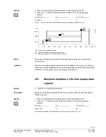
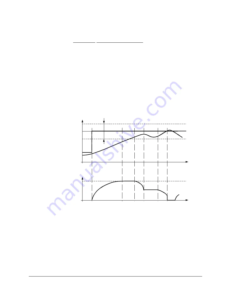
This temperature-time integral generates the locking signal for restricting the heating
circuits.
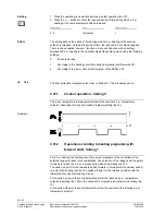
When generating the locking signal, one of four different procedures is used:
Diagram
Procedure
a to b
Within a foreseeable period of time, the actual value of the boiler
temperature (TKx) will
no
longer be within the switching differential of
the boiler temperature setpoint.
Locking signal will be increased
b to c and
d to e
Within a foreseeable period of time, the actual boiler temperature (TKx)
will lie within the switching differential of the boiler temperature setpoint.
Locking signal will remain at a constant level
c to d and
e to f
Within a foreseeable period of time, the actual boiler temperature (TKx)
will lie
above
TKw.
Locking signal will be decreased
f
The actual boiler temperature (TKx)
exceeds
the boiler temperature
setpoint.
Locking signal will be set to 0 %.
a
Start of d.h.w. heating
TK Boiler
temperature
TKw Boiler temperature setpoint
TKx
Actual value of the boiler temperature
SDK Boiler’s switching differential (factory setting 8K)
t Time
Y Locking
signal
Temperature-time
integral
Example:
TKx
23
78
Z1
1
t
a
b
TK
TKw
0%
t
y
x%
c
d
e
f
SDK
y

