17/184
Siemens Building Technologies
Basic Dokumentation RVA63.280, RVA53.280
CE1P2374E
Landis & Staefa Division
19.04.2001
2.3
Commissioning
To commission the controller:
•
Make certain that mounting and electrical installation are in compliance with the
relevant requirements
•
Make all plant-specific settings as described in section "Parameter settings"
•
Reset the attenuated outside temperature
•
Make the functional checks
2.3.1
Functional checks
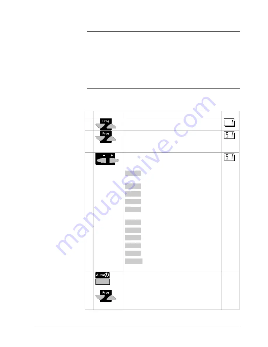
To facilitate commissioning and fault tracing, the controller allows output and input tests
to be made. With these tests, the controller’s inputs and outputs can be checked.
Buttons
Explanation
Line
1
Press one of the line selection buttons.
This will take you to the programming mode.
2
Press both line selection buttons for at least 3
seconds.
This will take you to the programming mode “Heating
engineer” and, at the same time, to the output test.
3
Press the + or - button repeatedly, which will take you
one test step further:
Test step 0
All outputs are switched according to normal control
operation
Test step 1
All outputs are deactivated
Test step 2
Burner stage 1 (K4) is activated
Test step 3
Burner stages 1 and 2 (K4 + K5) are activated
Test step 4
D.h.w. charging pump / diverting valve (Q3 / Y3) is
activated
Test step 5
Heating circuit 1 / boiler pump (Q2) is activated
Test step 6
Mixing valve HC1 OPEN (Y1) is activated
Test step 7
Mixing valve HC1 CLOSED (Y2) is activated
Test step 8
Heating circuit pump HC2 (Q6) is activated
Test step 9
Mixing valve HC2 OPEN (Y5) is activated
Test step 10
Mixing valve HC2 CLOSED (Y6) is activated
4
By pressing any of the operating mode or line
selection buttons, you leave the programming mode
and thus the output test.
Note:
If no button is pressed for about 8 minutes, the
controller will automatically return to the operating
mode selected last.
Prerequisites
Output test


