68/184
Siemens Building Technologies
Basic Dokumentation RVA63.280, RVA53.280
CE1P2374E
Landis & Staefa Division
19.04.2001
2.2
Input test
Commissioning is facilitated.
Faults can be pinpointed faster.
Also termed sensor test, which is used to check the wiring and the configuration.
Setting range
Unit
Factory setting
0...9
Increment
0
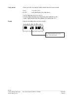
The input test will automatically become available on this line.
With each test step, the respective input will be displayed so that it can be checked.
The test sequence is arranged in the form of a ring counter. This means it can be run
through either forward or backward by pressing the + / - buttons.
For more information, refer to "commissioning" in Index.
Test step 0
Display of boiler temperature acquired with sensor B2
Test step 1
Display of d.h.w. temperature acquired with sensor B3
Test step 2
Display of input B31/H2 according to the function selected on line 174 [°C or ooo or ---].
Test step 3
Display of flow temperature HC1 acquired with detector B1
Test step 4
Display of flow temperature HC2 acquired with sensor B12
Test step 5
Display of outside temperature acquired with sensor B9
Test step 6
Display of room temperature acquired with room unit connected to A6
Test step 7
Display of room temperature acquired with room unit connected to A7
Testschritt 8
Display of the flue gas temperature acquired with sensor B8
Testschritt 9
Display of input H1 according to the function selected on line 170 [°C / 000 / - - -].
Benefit
Description
Setting
Effect
Test sequence
Note


