77/130
Siemens Building Technologies
Basic Documentation RVD230
CE1P2383en
HVAC Products
19 Function block Valve actuator d.h.w.
27.05.2004
19
Function block Valve actuator d.h.w.
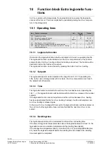
19.1 Operating
lines
Line
Function, parameter
Unit
Factory
setting
Range
111
Opening time actuator of d.h.w. circuit
s
35
10…873
112
Closing time actuator of d.h.w. circuit
s
35
10…873
113
P-band of d.h.w. control
K
35.0
1.0…100.0
114
Integral action time of d.h.w. control
s
35
10…873
115
Derivative action time of d.h.w. control
s
16
0…255
116
Setpoint boost d.h.w. charging
K
16
0…50
117
Maximum setpoint of d.h.w. temperature
°C
65
20…95
118
Setpoint boost mixing valve / heat exchanger d.h.w.
K
10
0…50
119
Reduced d.h.w. setpoint for storage tank sensor at the bottom
K
5
0…20
120
Circulating pump for d.h.w. charging
0
0 / 1
124
Load limit for actuation of flow switch
%
25
0…60
19.2 Mode of operation
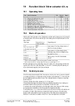
This function block provides d.h.w. temperature control with a mixing valve, 2-port valve
or diverting valve. The sensor and the type of actuating device required depend on the
type of plant:
Plant type
Sensor for con-
trolled variable
Regulating unit
1–3 B72*
0–x, 1–4, 1–8, 1–9,
1–10, 5–4, 5–9, 5–10
B3
2-port valve Y5 in the primary return of
the d.h.w. heat exchanger
2–11
B1
2–12 B1**
2-port valve Y1 in the primary return
(diverting valve Q3 is controlled by the
demand for d.h.w.)
6–2, 6–7
B3
2–2, 2–7
B3
3–2, 3–7, 7–2
B3
Mixing valve Y5 in the intermediate
circuit
* With no maximum limitation of the return temperature, 2-position control is used
** Same function as with d.h.w. heating using 2 flow sensors, e.g. plant types 2–7, 6–7
With the plant types using a diverting valve (2–11 and 2–12), the opening and the clos-
ing time are to be set on operating lines 111 and 112. The setting impacts passing on
of the heat demand signal to the heat exchanger.
19.3 Control
process
If the flow temperature deviates from the setpoint, the 2-port or mixing valve is adjusted
in a stepwise fashion to compensate for the deviation (with plant type 1–3, this can also
be accomplished with 2-position control). The controller drives an electric or electrohy-
draulic actuator.
The ideal running time of the actuator is 30…35 seconds.
The actuator’s opening and closing times are separately adjustable, thus making cer-
tain that actuators with asymmetric running times can also be used.
To enhance the control performance, the derivative action time (D-part of PID control)
can be adjusted, in addition to the P-band and the integral action time.
If, with plant type 1–3, no return sensor B72 is used, the function block will operate as a
2-position controller. When there is a demand for heat, 2-port valve Y5 will be fully
opened; with no demand for heat, it is fully closed. This takes place independent of
whether or not maximum limitation of the d.h.w. return temperature is activated.

