33/46
Siemens
Heating controllers RVP201 and RVP211
CE1P2464en
Building Technologies
4 Handling
2017-07-21
4 Handling
4.1 Operation
4.1.1 Operating
elements
24
64
Z
06
3
2
1
4
5
6
7
13 12
11
10
9
8
7
4
2
1
24
23
22
21
20
17
14
15
16
18
19
6
5
3
1
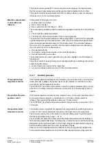
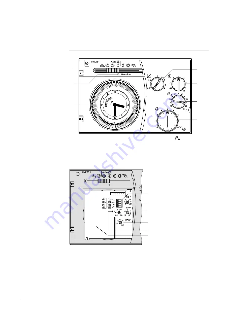
Slider for selecting the operating mode (the RVP201 does not have the position
)
2 LED (lit when operating mode is overridden; flashes when a fault is present)
3 Time
switch
4 Setting knob for slope of heating curve
5 Setting knob for setback to the reduced temperature
6 Setting knob for the d.h.w. temperature (not available with the RVP201)
7 Setting knob for the normal temperature; the zero-setting corresponds to a room temperature of 20 °C
Override
24
64
Z
07
1
2
3
6
5
4
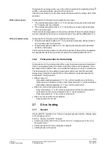
1 Coding switches
2 Setting potentiometer for the switching differential
3 Setting potentiometer for the ECO temperature
4 Setting potentiometer for maximum limitation of the flow or boiler temperature
5 Setting potentiometer for the authority of the room temperature and quick setback active / inactive
6 Space for the time switch
Operating elements for
the user
Operating elements for
the installer


