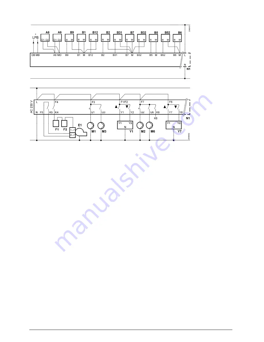
Connection diagrams
Low-voltage side
* LPB only RVP360
Mains voltage side
A6 Room unit
F1 Thermal reset limit thermostat
B1 Flow sensor heating circuit 1
F2 Safety limit thermostat
B12 Flow sensor heating circuit 2
K6 Multifunctional output
B2 Boiler sensor
LPB Data bus (only RVP360)
B31 D.h.w. storage tank sensor / thermostat
M1 Circulating pump
B32 D.h.w. storage tank sensor / thermostat
M2 Heating circuit pump heating circuit 1
B5 Room sensor heating circuit 1
M3 Storage tank charging pump
B52 Room sensor heating circuit 2
M6 Heating circuit pump heating circuit 2
B6 Collector sensor
N1 Controller RVP36..
B7 Return sensor
Y1 Actuator heating circuit 1
B9 Outside sensor
Y7 Actuator heating circuit 2
E1 2-stage
burner
Siemens Building Technologies
74 319 0817 0 a
CE1G2546en
28.02.2011
3/12


