
Siemens Building Technologies
A6V10464930_enGB_
a
b
2017-03-09
1/2
RWB29Si Installation instruction
Please take a little time to fully read these installation and user instructions so as to gain the most from your RWB29Si.
1. Programme Choice
To enable you to select the programme most suitable for your needs we offer a choice of 3 programmes:
-
Daily; Which means the unit will come ON and go OFF at the same times each day.
-
Weekday/Weekend; Which means the unit can be altered for weekdays and weekends.
-
7 Day; Which means the unit can be set to come ON and go OFF differently on every or any day.
Please refer to the dipswitch positions on below section dipswitches
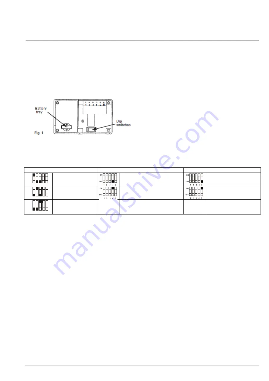
2. Dipswitches
To change the dipswitch positions first switch off the mains supply and then remove the unit from its backplate by simply loosen-
ing the two screws and pulling towards you.
Program choice
with DIP# 1, 2 & 3
ON/OFF switching periods
with DIP# 4
System type
with DIP# 5
1 2 3 4 5
ON
OFF
Daily
Two ON/OFF periods per day
Gravity system (10)
1 2 3 4 5
ON
OFF
Weekday/Weekend
Three ON/OFF phases per day
Fully pumped system (16)
1 2 3 4 5
ON
OFF
7 Day
When you have completed the changes to the dipswitches, replace the unit onto its backplate and then refer to the booklet sup-
plied with the unit that relates to the programme you have selected: Daily Programming, Weekday/Weekend Programming or
7 Day Programming.
This leaflet will help you to install and commission your programmer easily and quickly.
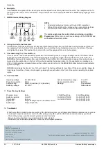
3. Installation
1.
First remove the backplate from the RWB29Si
by undoing the two small screws at the base of the unit and lift out from the
bottom so that the two lugs at the top disengage from their positions.
2.
The RWB29Si is factory set to provide 2 on/off switching periods per day and each day will be the same
, i.e. daily
operation. To select the other styles of switching you will have to alter the dip switches which are to be found at the bottom
rear of the unit (see Fig. 1) into the relevant position for the style of operation you require. See section 2 for dip[ switch set-
ting.
Note:
Press RESET after any dip switch change.
3.
Once you have completed the above you are now ready to connect the RWB29Si to the backplate
, If the RWB29Si is
replacing another Landis & Gyr or Landis & Staefa product as listed below no wiring changes are required, RWB1, RWB2,
RWB20, RWB40, RWB200, RWB200cw, RWB252, RWB252cw, RWB270, RWBXP, Gloworm Mastermind, Potterton
Miniminder, Sankey Sunline.
4.
If the RWB29Si is replacing another Landis & Gyr or Landis & Staefa product as listed below
, these products are NOT
suitable for replacement by the RWB29Si. Return the RWB29Si to your stockist/installer and request the RWB27Si which will
fully interface with your old unit’s backplate. with the exception of the RWB3 which will require a link inserted from L to 2 on
the existing backplate RWB3, RWB7, RWB30, RWB50, RWB100, RWB152, RWB152cw, RWB170 and RWBXT.
5.
Mounting Location
To ensure convenience of use, the RWB29Si should be fitted in a position which allows easy access. It is recommended that
the unit is placed at a height of 1.4 meters’ from the floor, and should not be installed where either extremes of heat or cold
exist. Care should also be taken to ensure that steam, water or oil cannot splash onto or enter either the RWB29Si or its


