Application Guide Quick Reference
RWD Controllers 44U/45U/62U/68U
Document Number 125-3511
March 28, 2005
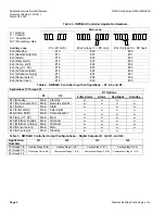
Table 3. RWD44U Controller Application Numbers.
Main Loop
H = Heating
C = Cooling
Cr = Compressor
RV = Reversing valve
RV
RV
Auxiliary Loop
#1x (2H & 2C)
#2x (3-stage Cr + RV cool)
# 3x (3-stage Cr + RV heat)
#x0 (Standby)
#10
#20
#30
#x1 (Remote setpoint)
#11
#21
#31
#x2 (Alarm)
#12
#22
#32
#x3 (Filter alarm)
#13
#23
#33
#x4 (Comp. shift)
#14
#24
#34
#x5 (Avg. X1, X2)
#15
#25
#35
#x6 (Win/Sum digital)
#16
#26
#36
#x7 (Win/Sum analog)
#17
#27
#37
#x8 (Sensor select)
#18
#28
#38
#x9 (Active input)
#19
#29
#39
Table 4. RWD44U Controller Input Configurations – X1, X2, and D1.
Applications 10 Through 39
D1 Options
X1
X2
Filter Alarm
Alarm
Day/Night
Standby
#x0 (Standby)
Main
Standby
♦
♦
♦
–
#x1 (Remote setpoint)
Main
Remote setpoint
♦
♦
♦
♦
#x2 (Alarm)
Main
Alarm
♦
–
♦
♦
#x3 (Filter alarm)
Main
Filter alarm
–
♦
♦
♦
#x4(Comp. Shift)
Main
Compensation
♦
♦
♦
♦
#x5 (Avg. X1, X2)
Main
Main
♦
♦
♦
♦
#x6 (Win/Sum Digital)
Main
Win/Sum
♦
♦
♦
♦
#x7 (Win/Sum Analog) Main
Win/Sum
♦
♦
♦
♦
#x8 (Sensor select)
Main Main
♦
♦
♦
♦
#x9 (Active input)
Main
Standby
♦
♦
♦
–
Table 5. RWD44U Controller Output Configurations – Digital Outputs Q1, Q2, Q3, and Q4.
Application
Numbers
Q1
Q2 Q3 Q4
10 through 19
Heating Stage 2 (H2)
Heating Stage 1 (H1)
Cooling Stage 1 (C1)
Cooling Stage 2 (C2)
20 through 29
30 through 39
Reversing Valve (RV)
Compressor Stage 1 (Cr1)
Compressor Stage 2 (Cr2)
Compressor Stage 3 (Cr3)
Page 2
Siemens Building Technologies, Inc.


