Page 8
8-Jun-01
O3341(RWD32) V14.doc
O3341A031En2
Siemens Building Technologies
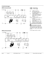
Connection Diagram
RWD82 Connection Diagram
G
S1
D1
G0
B M
B M
X1
X2
M
M
X2
X1
M
G0
G AC 24 V
Q12 Q14
(N)
RWD82
Q11
Y1
Y1
Q22 Q24
Q12 Q14 Q22 Q24
Q11
Q21
Q21
Y2
G0
1.
2.
Q1
Q2
Q1
Q2
E1
N1
TOOL
PC
G
G
G0
G AC 24 V
(L) AC 230 V
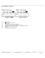
RWD82 – AC 24 V supply
RWD32 – AC 230 V supply
N1
RWD82/32 controllers
X1
Main temperature sensor
(Termination G appears when X1
is an active sensor)
X2
Auxiliary temperature sensor or
remote setpoint (Termination G
appears when X2 is an active
sensor)
S1
Time clock or switch
Q1/Q2 Potential-free relay contacts for 3-
position or
2-position control in 2 steps
Y1
Actuator with 3-position control
(AC 24...230 V)
E1
Electrical load 2-position control
PC
Desktop or notebook computer
Note: Output relay contacts (potential free)
can be supplied with AC 24 to 230 volts.
RWD32 Connection Diagram
L
S1
D1
N
B M
B M
X1
X2
M
M
X2
X1
M
Q12 Q14
L AC 230 V
N
RWD32
Q11
Y1
Y1
Q22 Q24
Q12 Q14 Q22 Q24
Q11
Q21
Q21
Y2
N
1.
2.
Q1
Q2
Q1
Q2
E1
N1
TOOL
PC
G0
(N)
G AC 24 V
(L) AC 230 V
G AC 24 V
G0
G
G
Please note that the TOOL signal
ground is galvanically connected to G0
inside the controller. If the signal line of
the computer is grounded to Earth, the G0
line after TOOL connection will be Earthed
as well.
This will change the SELV to a PELV.

