background image

8/10

Siemens

RWD62 Universal controller

CE2N3342en

Building Technologies

2017-12-05

Disposal

Technical data

Operating voltage

Safety extra-low voltage (SELV) as per
Frequency

AC 24 V

±

20 %

EN 60730
50 Hz/60 Hz

RWD62

2.5 VA

Actual and nominal values

4 digits

LG-Ni 1000
Pt 1000
Active sensor

0.5 °C
0.5 °C
Depends on the setting range

Transport

Climatic conditions
Temperature
Humidity
Mechanical conditions

IEC721-3-2
Class 2K3

-

25…

+

70 °C

<95 % r.h.
Class 2M2

Operation

Climatic conditions
Temperature
Humidity

IEC721-3-3
Class 3K5
0…

+

50 °C

<95 % r.h.

Housing

Front and with ARG62.21
Front and with ARG62.22

IP 20 as per EN 60529
IP 30 as per EN 60529

EU Conformity (CE)
RCM Conformity

CE2T3341xx *)
CE2T3341en_c1 *)

The product environmental declaration CE1E3343en *) contains data on environmentally
compatible product design and assessments (RoHS compliance, materials composition,
packaging, environmental benefit, disposal).
Screw terminals for cables with

min. 0.5 mm dia.
max. 2 x 1.5 mm

2

 or 2.5 mm

2

RWD62

0.277 kg

*)

The documents can be downloaded from http://siemens.com/bt/download.

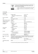
The device is considered electrical and electronic equipment for dis-
posal in terms of the applicable European Directive and may not be
disposed of as domestic garbage.

·

  Dispose of the device through channels provided for this purpose.

·

  Comply with all local and currently applicable laws and regula-

tions.

General data

Po

w

er supply

Power consumption

LCD

Display resolution for (these
values do not relate to the
controller accuracy)

Environmental
conditions

Environmental
conditions

IP code

Norms and standards

Terminals

Weight without packag-
ing

Environmental compati-
bility

Summary of Contents for RWD62

Page 1: ...Pt 1000 temperature sensors and DC 0 10 V signals Unit can be set as C F or no specified unit Two modulating outputs with DC 0 10 V signal outputs direct or reverse action One digital input for day night changeover Entering or changing of all data via operating buttons on the controller possi ble without additional tools PC connection for downloading canned applications via the software tool Use T...

Page 2: ...ction Cascade control function Setpoint compensation Winter summer operation Maximum priority Digital input D1 for setpoint changeover day night Type summary Inputs Outputs Type Reference Universal Digital Analog Digital 2 1 2 0 RWD62 Name Type Protective small enclosure for wall mounting ARG62 21 Protective big enclosure for wall mounting ARG62 22 Software Tool S3341A031EN0 Equipment combinations...

Page 3: ...on and setting parameters via the push buttons on the controller or the software tool The RWD62 controller can be programmed as follows One sequence Y1 or Y2 reverse or direct acting Two sequence Y1 and Y2 reverse and direct acting or Y1 and Y2 reverse and reverse acting or Y1 and Y2 direct and direct acting Y1 Output Voltage Setpoint Load 3342d01 3342d02 Y1 Output Voltage Load Y2 Setpoint Reverse...

Page 4: ...3342s01 One of the following auxiliary functions can be selected PI limiter function absolute and relative Remote setpoint function Cascade control function Setpoint compensation Winter summer operation Maximum priority Additionally the day and night operation mode is available The limiter function with PI control enables absolute or relative maximum or minimum limitation of the supply air tempera...

Page 5: ...perature setpoint as controlled by the outside temperature 3342s06 X2 Y1 Temp RWD62 Y X1 A digital switch or analogue input between termi nals X2 and M can be used to implement win ter summer changeover Digital changeover When the contact is closed summer operation is selected Reverse acting output Y1 only is set to direct action cooling Analog changeover When the X2 input exceeds the setpoint sum...

Page 6: ...ated by the buttons on the controller front Additional tools are not necessary A 9 pin port is provided for optional programming via the software tool 3342z01 The LCD shows the following information for normal operation Current operating values maximum 4 digits Current setpoints day night Application number Output voltage value Control sequencing diagram Auxiliary input value Selected auxiliary fu...

Page 7: ... AC 24 V operating voltage The low voltage must comply with the requirements for safety extra low voltage SELV as per EN 60730 Use safety insulating transformers with double insulation as per EN 60742 they must be designed for 100 on time When using several transformers in one system the connection terminals G0 must be galvanically connected Supplying voltages above AC 24 V to low voltage connecti...

Page 8: ...duct environmental declaration CE1E3343en contains data on environmentally compatible product design and assessments RoHS compliance materials composition packaging environmental benefit disposal Screw terminals for cables with min 0 5 mm dia max 2 x 1 5 mm2 or 2 5 mm2 RWD62 0 277 kg The documents can be downloaded from http siemens com bt download The device is considered electrical and electroni...

Page 9: ...for control commands D M Current consumption DC 15 V 15 mA Range Maximum current DC 0 10 V 1 mA Internal diagram G0 RWD62 Y2 D1 M X1 M X2 M G M Y1 M Tool 3342g01 D1 Digital input G G0 AC 24 V supply SELV AC 24 V power supply M Ground G0 for signal inputs universal inputs and analog outputs X1 Signal input main input LS Ni 1000 Pt 1000 and 0 10 V DC X2 Signal input aux input LS Ni 1000 Pt 1000 0 10...

Page 10: ...P computer the TOOL signal ground is gal vanically connected to G0 inside the controller If the signal line of the computer is grounded to Earth the G0 line after TOOL connection will be Earthed as well This will change from SELV to a PELV Dimensions ARG62 21 150 200 61 5 48 5 ARG62 22 345 Published by Siemens Switzerland Ltd Building Technologies Division International Headquarters Gubelstrasse 2...

Reviews: