Technical Instructions
RWD68U Universal Controller
Document Number 155-738
January 14, 2005
Software Tool
An optional, user-friendly, Windows® 95 (or later) based software tool for controller
application selection and parameter adjustment is available. It provides you with a
printout of the controller settings. This tool allows controller programming prior to
installation.
Functions
Controller Type
The RWD68U is a stand-alone universal controller, which performs both primary and
auxiliary control functions. The respective mode is defined by entering the
corresponding configuration and setting parameters via the push buttons on the
controller or the software tool.
Main Functions
The RWD68U controller can be programmed as follows:
•
One sequence:
Q1
Reverse or direct acting
•
Two sequences: Y1 and Q1 Reverse and direct acting or
Y1 and Q1 Reverse and reverse acting (independent
and dependent control loop) or
Y2 and Q1 Direct and direct acting (independent and
dependent
control
loop)
NOTE:
Direct Acting – As air temperature increases, the control output increases.
Reverse Acting – As air temperature increases, the control output
decreases.
TH0599R3
= TEMPERATURE SENSOR
= AIR DAMPER ACTUATOR
= HEATING COIL
= COOLING COIL
= HEATING OR COOLING COIL (TWO-PIPE)
= FAN OR PUMP
= TIME CLOCK
= REMOTE SET POINT UNIT
= OUTSIDE AIR SENSOR
+
+
-
-
Figure 1. Frequently Used Symbols in Application Drawings.
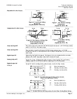
TH0746R1
OFF
ON
SD
SD
2
2
SD
Setpoint
Temp.
Figure 2. Reverse Acting Sequence
(Application 10 to 19).
TH0747R1
OFF
ON
SD
SD
2
2
SD
Setpoint
Temp.
Figure 3. Direct Acting Sequence
(Application 80 to 89).
TH0748R1
Y1
XP
OFF
Temp.
Setpoint
Heating
Cooling
Q1
SD
SD
SD
2
2
ON
Min V
O
uptut
V
o
lt
agee
Max V
Figure 4. Reverse and Direct Acting
Sequences
(Application 40 to 49).
TH0749R1
Y1
Min V
Temp.
Setpoint
Heating
Cooling
O
uptut
V
o
lt
agee
OFF
ON
Q1
SD1
SD1 SD1
2
2
Max V
Figure 5. Direct Acting Sequences
(Application 50 to 59).
Page 4
Siemens Building Technologies, Inc.


