92/93
Building Technologies Division
User Manual RWF55...
CC1U7867en
Infrastructure & Cities Sector
16 List of figures
05.11.2013
Modulating burner, analog output
.................... 24
Operating mode changeover
............................ 23
Predefined setpoint
........................................... 28
Response threshold (q)
..................................... 34
Setpoint changeover
SP1
/ external setpoint via
InP2
...................................................................... 30
Setpoint changeover
SP1
/
SP2
or setpoint shift
analog via
InP2
................................................... 29
Setpoint shifting
SP1
analog via
InP2
/ binary via
dSP
........................................................................ 31
Thermal shock protection
................................. 37
Thermostat function
.......................................... 22
Weather-compensated setpoint shifting
......... 33
Operation
................................................................. 38
3-position controller
.......................................... 42
Basic display
...................................................... 40
Basic display
...................................................... 38
Cancel
................................................................. 44
Changing the setpoints
..................................... 41
Display of software version
.............................. 45
Flashing actual value display
........................... 39
Initialization
........................................................ 38
Manual control
................................................... 39
Manual control, 2-stage burner
........................ 43
Manual control, modulating burner
.................. 42
Meaning of display and buttons
....................... 38
Modulating controller
........................................ 42
Parameter display
.............................................. 38
Segment test ........................................................ 45
Self-setting function
.......................................... 38
Start
..................................................................... 44
Starting the self-setting function
...................... 44
Timeout ................................................................ 41
User level
............................................................ 41
P
Parameterization
Display of controller parameters .......................... 47
Parameterization
PArA
............................................. 46
PC software ACS411
Measuring accuracy
.......................................... 67
Operating systems
............................................. 66
Powering the controller via the USB port
........ 67
Use of USB port
................................................. 67
Using the HUB
.................................................... 67
PC-Software ACS411
Switching off
...................................................... 67
Profibus-DP interface
.............................................. 72
Parameter list
..................................................... 77
RS-485 Technology transfer
............................. 72
Wiring
................................................................. 77
R
RS-485 Technology transfer
Basic features ..................................................... 72
Basic functions .................................................... 75
Bus terminator ..................................................... 73
Cable data ........................................................... 74
Cable length ........................................................ 72
Cyclical data traffic .............................................. 76
Data rate ............................................................. 74
Structure .............................................................. 72
Wiring and bus termination ................................. 75
S
Self-setting function
............................................... 62
2 procedures
...................................................... 63
Checking the controller parameters
................ 64
Conditions
......................................................... 63
Self-setting function in high-fire operation
.... 62
T
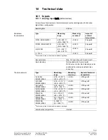
Technical data
......................................................... 79
Binary input D2
.................................................. 82
Controller
........................................................... 85
Controller outputs
OutP
..................................... 84
Electrical data
.................................................... 85
Environmental conditions
................................ 86
Housing
.............................................................. 85
Inputs
................................................................. 79
Monitoring the measuring circuit
.................... 83
Resistance thermometers ................................... 79
Segment display
................................................ 86
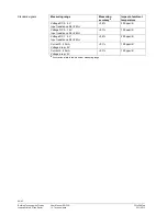
Standard signals ................................................. 80
Standards and certificates
............................... 86
Technical Data
Analog input
InP1
.............................................. 79
Analog input
InP2
.............................................. 81
Analog input
InP3
.............................................. 81
Binary input D1
.................................................. 81
Interface RS-485 ................................................. 84
Profibus interface ................................................ 84
Resistance thermometer ..................................... 81
Standard signals ................................................. 81
Thermal elements ............................................... 79
W
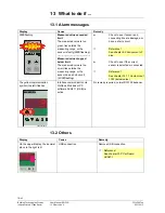
What to do if…
........................................................ 78
Alarm messages
................................................ 78
Others
................................................................. 78
Wiring
Assignment of 9-pole D-Sub jack ........................ 77

