background image

7

L

IFTING

 R

ECOMMENDATIONS

Weight (as shown)

350 lbs.

Weight (as shown)

700 lbs.

Mechanism only can be
lifted into place using the
lifting eye provided

1.  Signal assembly must be without

arm and counterweight.

2.  Lift point should be a minimum

of 15" above gate mechanism.

3. Lifting sling can be used around

mast and under the junction box
crossarm for lights as shown.

Recommendations for lifting pre-assembled
signals with gate mechansim.

Description

Adapter Cast
Adapter Fab
Conversion Bracket (cast adapter)
Conversion Bracke (fab adapter)
J. B. Base Assy.
Mast & J. B. Base (5" Alum.)
Mast & J. B. Base Stud (5" Alum.)
Sidelight Cantilever
Counterweight Std.
Counterweight Short
Counterweight Stud Plate

Arm Supports (1 each)

Arm Supports (1 each)
R.R. Crossing Sign w/mtg. Hardware
#2 Track Sign w/mtg. Hardware
J.B. Crossarm 2 Way w/FLX-12 Heads Complete
S-40EXIT Gate Mechanism
Galvanized Steel Foundation

Part Number

076203-510X
076203-501X
076227-X
076227-22X
041931-X
070519-27AX
070519-40AX
070519-3AX
041442-26X
070755-4
070755-34
070757-26X
070920-LX or
070921-RX
035200-17X or
035236-2X
042003-000616
074008-X
035903-911-1X

Dimensions

14 feet - 0 inches
16 feet - 0 inches
7 feet - 0 inches

15 x 30 x 1/2 inches
15 x 15 x 5/8 inches

Weight

28 lbs.
20 lbs.
75 lbs.
55 lbs.
85 lbs.
140 lbs.
160 lbs.
100 lbs.
38 lbs.
63 lbs.
38 lbs.
15 lbs.
72 lbs.
30 lbs. each
30 lbs. each
40 lbs.
25 lbs.
110 lbs.
350 lbs.
200 lbs.

Summary of Contents for S-40EXIT

Page 1: ...NG GATE NOVEMBER 2008 REVISED JANUARY 2014 DOCUMENT NO 074044 3 VERSION B Siemens Rail Automation Corporation 9568 Archibald Ave Suite 100 Rancho Cucamonga California 91730 1 800 793 SAFE Copyright 2013 Siemens Rail Automation Corporation All rights reserved ...

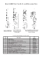
Page 2: ...p Bar Application 14 General Maintenance Motor Maintenance Tools Relays 15 Model S 40 EXIT Gate Type 50 51 and 52 Replacement Parts 16 Sidelight Cantilever Assembly and Replacement Parts 17 S 40EXIT Gate Replacement Parts 18 19 Terminal Board Assembly and Replacement Parts 20 Relay Panel Assembly Replacement Parts 21 Gate Arm Supports Counterweights Replacement Parts 22 Hardware Torque Guidelines ...

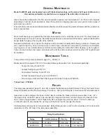
Page 3: ...ircuits A brake is used to hold the arm in both the vertical and horizontal positions With standard wiring as shown on page 3 positive and negative battery to terminal locations 4 5 is always present and serves to supply power to the motor An additional positive battery down control serves to energize the control relay K4 External switching by the user is required which will lower and hold the gat...

Page 4: ...ashing light control position 9 Adjustable contact and cam for bell control position 10 Adjustable horizontal snub contact and cam position 11 Note Contact cams are factory set as shown on wiring diagram page 3 Adjustable snub resistors to set up time and down time 80 ohm max 115 VAC Defroster located under motor end and wired to terminal block position 1 with insulated nuts Mechanism serial numbe...

Page 5: ...3 ...

Page 6: ... 4 anchor bolts part number 131702 26X are required RECOMMENDED BATTERY AND WIRE REQUIREMENTS Sizes of wire used for the motor circuit should be calculated so that there will be not more than 0 1 ohm resistance between the battery and mechanism terminals Wire sizes as follows are recommended The following battery is recommended with above wire sizes for gates of various lengths SteelFoundation 035...

Page 7: ... 18 items 73 74 8 Mount flashing lights bell and signs The flashing light units have been factory wired but control wires from the lights junction box to the junction box base must be field installed Align the flashing light units before placing the crossing in service Bell when used is mounted on top of the mast with the gong facing the roadway A spare contact is provided on the gate controller t...

Page 8: ... rotating contact cam 7 and operating gate with down control Be sure that horizontal buffer upper position is clear of segment gear See pages 8 and 9 13 Raise and check vertical position of arm Set the vertical position by rotating contact cam 8 and operating gate with up control see page 8 14 Adjust buffers Set both buffers to 1 32 clearance from segment gear per instructions on page 9 15 Set ver...

Page 9: ... B Base Stud 5 Alum Sidelight Cantilever Counterweight Std Counterweight Short Counterweight Stud Plate Arm Supports 1 each Arm Supports 1 each R R Crossing Sign w mtg Hardware 2 Track Sign w mtg Hardware J B Crossarm 2 Way w FLX 12 Heads Complete S 40EXIT Gate Mechanism Galvanized Steel Foundation Part Number 076203 510X 076203 501X 076227 X 076227 22X 041931 X 070519 27AX 070519 40AX 070519 3AX ...

Page 10: ...uare contact and a good wiping action when the contact closes Tension pressure of closed contact to be between 28 and 48 oz Contact tools and gages are available see page 15 for ordering information CAUTION Repeated or overbending of a contact may cause damage and not allow proper tension when closed or gap when open Contact cams are factory set for contact function as shown in the table below or ...

Page 11: ...wever if the gate arm is repositioned they will require readjustment as shown below To adjust the vertical buffer With arm vertical remove the cap and 3 16 cotter pin at the lower buffer Turn the nut to obtain 1 32 clearance between buffer and segment gear Replace cotter pin and cap To adjust the horizontal buffer With arm horizontal remove the cap and 3 16 cotter pin at the upper buffer Turn the ...

Page 12: ...st the torque direction as a false high reading will result 5 Close test terminal B pos 4 remove torque wrench and adjust counterweights as needed Vertical torque Set vertical torque to obtain a free position of 70 to 83 as follows 1 Close test terminal A pos 6 to lower arm to horizontal 2 Open test terminal B pos 4 allowing arm to raise to a free balanced condition 3 Check position of arm per dia...

Page 13: ...11 TORQUE ADJUSTMENTS VERTICAL TORQUE HORIZONTAL TORQUE LOOSEN INSIDE NUTS ROTATE LOCKING PIECE 900 SLIDE COUNTERWEIGHTS OBTAIN TORQUE RETURN LOCKING PIECE RETIGHTEN NUTS 700 830 900 00 ...

Page 14: ...e gate mechanism hand crank feature may be used either to crank the gate up or in a case where the arm has been sheared off to crank the counterweights to the horizontal position The tools required are a ratchet wrench with 3 8 inch drive a inch socket for 3 8 inch drive and a ratcheting box end wrench for inch hexagon shaft all of which are included in the Safetran Torque Wrench Kit 1 Place ratch...

Page 15: ...e OPERATING STEPS 1 Close test terminal A pos 6 and open test terminal B pos 4 2 Position the Stop Bar with key slot over the pivot lug in a ready position see next page 3 Depress and hold the Push Button until counterweights are fully raised 4 Rotate the Stop Bar end against the motor pinion teeth and release the Push Button 5 Install gate arm 6 Close test terminal B and replace stop bar 7 Open t...

Page 16: ...ts are fully raised rotate Stop Bar up against motor pinion teeth as shown and release the maintenance switch push button STORAGE POSITION Remove Stop Bar rotate it and place the key slot over the lower motor mount bolt head then rotate up with the notch under the pivot lug as shown HOLE FOR WIRE TIE KEYSLOT STOP BAR PIVOT LUG Stan dard ...

Page 17: ...tor with a lint free cloth Brushes worn to less than 3 4 length should be replaced MAINTENANCE TOOLS Torque Wrench Kit contents listed on page 12 070981 X Maintenance Kit Complete 073112 3X includes following items which can be ordered separately Contact Forming Tool 073112 Contact Setting Gage 073112 1 Commutator Cleaning Tool 073112 2 Contact Cleaning Strips box of 12 073000 15 Tension Gage for ...

Page 18: ...ounting 040200 4X 8 Bell 120 VAC Operation for 5 Mounting 040200 8X 9 Bell 12 16 VAC 10 12 VDC Operation for 5 Mounting 040200 10X 10 Pinnacle 5 035045 503X 11 Sign Railroad Crossing for 5 Mounting 035200 17X 12 Sign Track for 5 Mounting specify of tracks 035236 X 13 Lamp Flashing See flashing lamp section of catalog Specified 14 Mechanism S 40EXIT Gate 074008 X 15 Cantilever Sidelight required fo...

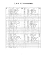
Page 19: ... 2 13 x 2 2 4170 HSC 10 Cap Screw Hex Head 3 4 10 x 6 2 4286 HSC 11 Cap Screw Hex Head 1 2 13 x 6 1 4182 HSC 12 Cap Screw Hex Head 1 2 13 x 5 4 4180 HSC 13 Washer Wrought 1 2 7 1755 C 14 Washer Spring Lock M 1 2 7 1812 MSC 15 Washer Spring Lock M 3 4 7 1815 MSC 16 Nut Hex 1 2 13 7 2108 SC 17 Nut Hex 3 4 10 2 2114 SC 18 Washer Flat 3 4 4 1737 SC Part Number Qty Req d Description Item No FOR COMPLET...

Page 20: ...18 S 40EXIT Gate Exploded View ...

Page 21: ...19 S 40EXIT Gate Replacement Parts ...

Page 22: ...074030 4XR Item No 1 2 3 4 5 6 7 8 9 10 Qty 12 24 12 36 5 5 5 5 5 1 Part No 010427 6 023831 023832 023834 070627 041414 073012 2 073012 X 073011 X 070625 Description Terminal Post Nut Binding Nut Clamp Washer Beveled Washer Insulating Bushing Insulating Spring Reinforcing Contact Fixed Front Contact Moveable Back Board Terminal ...

Page 23: ...RTS Item No 1 2 3 4 5 6 Qty 8 1 1 1 2 1 Part No 023835 40X 074046 2 002560 RSC 074015 X 002572 1 092431 81 Description Terminal Post Assembly Circuit Breaker 7A Auto Screw RD HD 4 40 X 5 8 Overspeed Module Screw Pan HD 10 32 X 3 8 Pushbutton To order specify description and part number ...

Page 24: ...te 070925 X 9 Cap Screw Hex Head 1 2 13 x 1 25 4167 HSC 10 Washer Wrought 1 2 1755 C 11 Nut Hex 3 4 10 2114 SC 12 Washer Wrought 3 4 1737 SC 13 Washer Spring Lock M 3 4 1815 MSC 14 Cap Screw Hex Head 3 4 10 x 3 for 3 4 standard counterweights 4278 HSC Cap Screw Hex Head 3 4 10 x 4 for 5 6 standard counterweights 4282 HSC Machine Bolt Hex Head 3 4 10 x 6 5 for 7 10 standard counterweights 3177 SC 1...

Page 25: ...23 HARDWARE TORQUE GUIDELINES Thread Size 1 4 20 5 16 18 3 8 16 1 2 13 5 8 11 3 4 10 1 8 Hex Nut Size 7 16 1 2 9 16 3 4 15 16 1 1 8 1 1 2 Torque Ft Lb 6 15 25 55 90 105 140 ...

Page 26: ...TWO SUPT ARMS REQ D 1XT 1 COUNTERWEIGHT EXTENDED UP W SUPPORT BRACKET 2XT 2 COUNTERWEIGHTS EXTENDED UP W SUPPORT BRACKET 6 5 1XT 8 8 10 10 12 12 14 14 14 16 16 18 18 20 20 24 24 SHORT COUNTERWEIGHTS REQUIRED WITH GATE PROTECTION DEVICES ONE SUPT ARM REQ D Arm Length NEG Gate GSI Gate Keeper 12 14 16 18 20 22 24 26 28 30 32 34 36 38 40 42 44 46 6 3 3XT 8 7 1XT 8 6 2XT 10 12 12 14 14 16 16 18 18 20 ...

Page 27: ......

Page 28: ...ation Corporation 2400 Nelson Miller Parkway Louisville Kentucky 40223 502 618 8800 Siemens Rail Automation Corporation California R D Division 9568 Archibald Ave Suite 100 Rancho Cucamonga California 91730 909 532 5300 ...

Reviews: