Internal Accessories
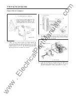
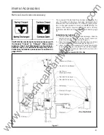
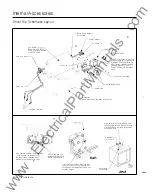
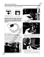
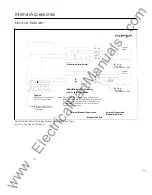
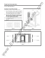
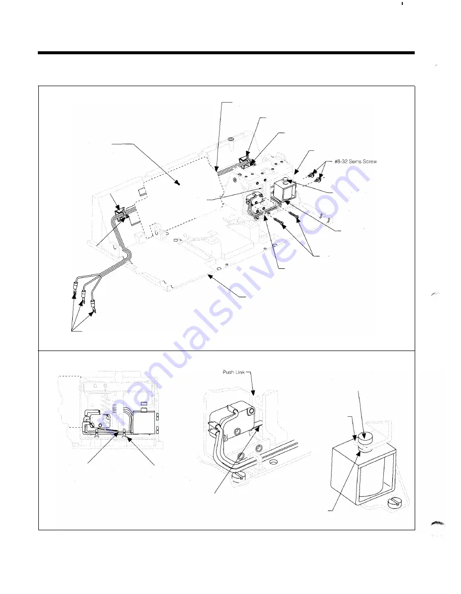
Shunt Trip Schematic Layout
W1re Shield
(Shown for 800-2000A
frame, no shield required
for 4000A frame.)
Cable Tie Mount
\
\
Cable Tie
__//
Insulated Terminal
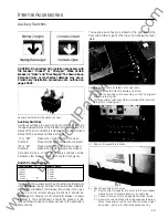
Insert sw1tch actuator lever into side
cavity of push link (see deta1l A).
Switch must be actuated when
breaker ma1n contacts are open.
Shunt Trip Installation
54
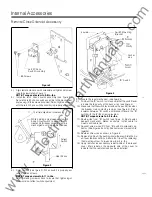
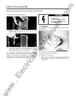
Route Wires Beneath
W1re Shield
Cable Tie Mount
Cable Tie
Secondary Latch
_-
Insert Plunger Groove I nto Fork
t' -
Push L1nk
�
@
- - - - - - - - 'o
o >
Of Secondary Latch (See Detail
B, Below) Check For Bmd1ng
After T1ghten1ng #8 Screws By
Press1ng Down On Top Of
Plunger To Operate Secondary
Latch
Shunt Tnp Assembly
#4 40 Nylok Screw
Wire Guide
M1d barrier
Note: Mechanism Not Shown For Clarity.
Push here to check for binding after
tightening #8 screws. Plunger should
move freely and be freely returned by
secondary latch.
Secondary
Latch Fork
Insert w1res into wire
guides after installing
sw1tch and soleno1d
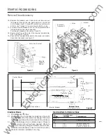
Detail A
Scale 2/1
Insert Switch Actuator Lever into side
cavity of push link. Lever should rest
on the push link ledge as shown when
breaker is open.
Secondary
Latch Fork
Detail
B
Scale 2/1
www
. ElectricalPartManuals
. com

