Frame Installation Instructions
1 1
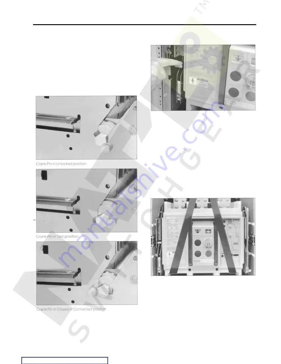
To properly engage the moveable drawout element with the
racking mechanism, the crank pins on the sides of the
moveable drawout element must be in the “unlocked’’
position as illustrated and the interlock lever is in the “up’’
position. During shipping and handling the crank pins may
have rotated out of position. If so, rotate them to the proper
position. The moveable drawout element may now be moved/
racked into the stationary drawout element. Racking instruc-
tions are located in the Operating Instructions section.
Moveable Drawout Element and Fixed-Mounted SB Breakers
Interlock Lever mechanism
Installing Fixed-Mounted SB Breakers
Prepare the switchboard for installation of the SB breaker in
accordance with the outline drawings at the end of this
section. The outline drawing for the 800A and 1200A frame
is located on pages 90-91. The outline drawing for the 2000A
frame is located on pages 92-93. The locations of the
mounting holes and the recommended screws are depicted
on the drawing . All four mounting screws will be used to
secure the breaker to the switchboard.
Carefully uncrate the breaker and remove all packing mate-
rial. The keys for a breaker with a key interlock accessory will
be taped to the top of the breaker. If the breaker is secured
to a pallet, remove the securing device.
Lifting straps should go between the stabs.
Attach the lifting straps as illustrated. The breaker should not
be lifted by the primary stabs; the lifting straps should go
between the stabs. In this arrangement the breaker may be
easily balanced while it is being lifted by a crane or hoist.
Lift the breaker into position and secure it with all four
mounting screws torqued to 15 ft. lbs. max. Remove the
lifting straps.
Summary of Contents for SBA 1200
Page 68: ...66 External Accessories Ground Fault Sensing and Relaying Courtesy of NationalSwitchgear com ...
Page 94: ...92 Outline Dimension Drawing 2000A Fixed Mounted Courtesy of NationalSwitchgear com ...
Page 95: ...93 Outline Dimension Drawing 2000A Fixed Mounted Courtesy of NationalSwitchgear com ...
Page 100: ...98 Courtesy of NationalSwitchgear com ...
Page 101: ...Electrical Diagrams 99 Courtesy of NationalSwitchgear com ...
Page 102: ...100 Electrical Diagrams Courtesy of NationalSwitchgear com ...


