External Accessories
65
Test Operation
GF Type Switch set to RESIDUAL
Outgoing Circuit Method (if trip unit does not provide
ground fault protection, this is the method used.)
3 Phase / 3 Wire
Using Figures 2, and 1 or 5, individually test breaker poles A,
B, and C, for proper Ground Fault operation.
Each of the circuit breaker s front panel controls should be set
to the highest setting. Set the Ground Fault Monitor to the LO
pickup on the .1 second delay band. Using a low voltage
current source, apply a test current equal to 50% of the rating
plug value. The circuit breaker must trip.
3 Phase / 4 Wire
Using Figures 3, and 1 or 5, individually test breaker poles A,
B, and C, in conjunction with the proper neutral sensor for
Ground Fault operation.
Ground Fault Sensing and Relaying
Each of the circuit breaker s front panel controls should be set
to the highest setting. Set the Ground Fault Monitor to the LO
pickup on the .1 second delay band. Using a low voltage
current source, apply a test current equal to 50% of the rating
plug value. The circuit breaker must not trip . Reduce the test
current to zero.
Using a suitable means, short the X1 wire and the X2 wire
connections together on the Neutral Sensor. Reapply a test
current equal to 50% of the rating plug value. The circuit
breaker must trip. Reduce the test current to zero and remove
the shorting means from the Neutral Sensor.
GF Type Switch set to GROUND RETURN
Ground Return Method
3 Phase / 3 Wire or 3 Phase / 4 Wire
Using Figures 4 and 1 or 5, individually test breaker poles A,
B, and C, for proper Ground Fault operation.
Each of the circuit breaker’s front panel controls should be set
to the highest setting. Set the Ground Fault Monitor to the LO
pickup on the .1 second delay band. Using a low voltage
current source, apply a test current equal to 50% of the rating
plug value. The circuit breaker must trip.
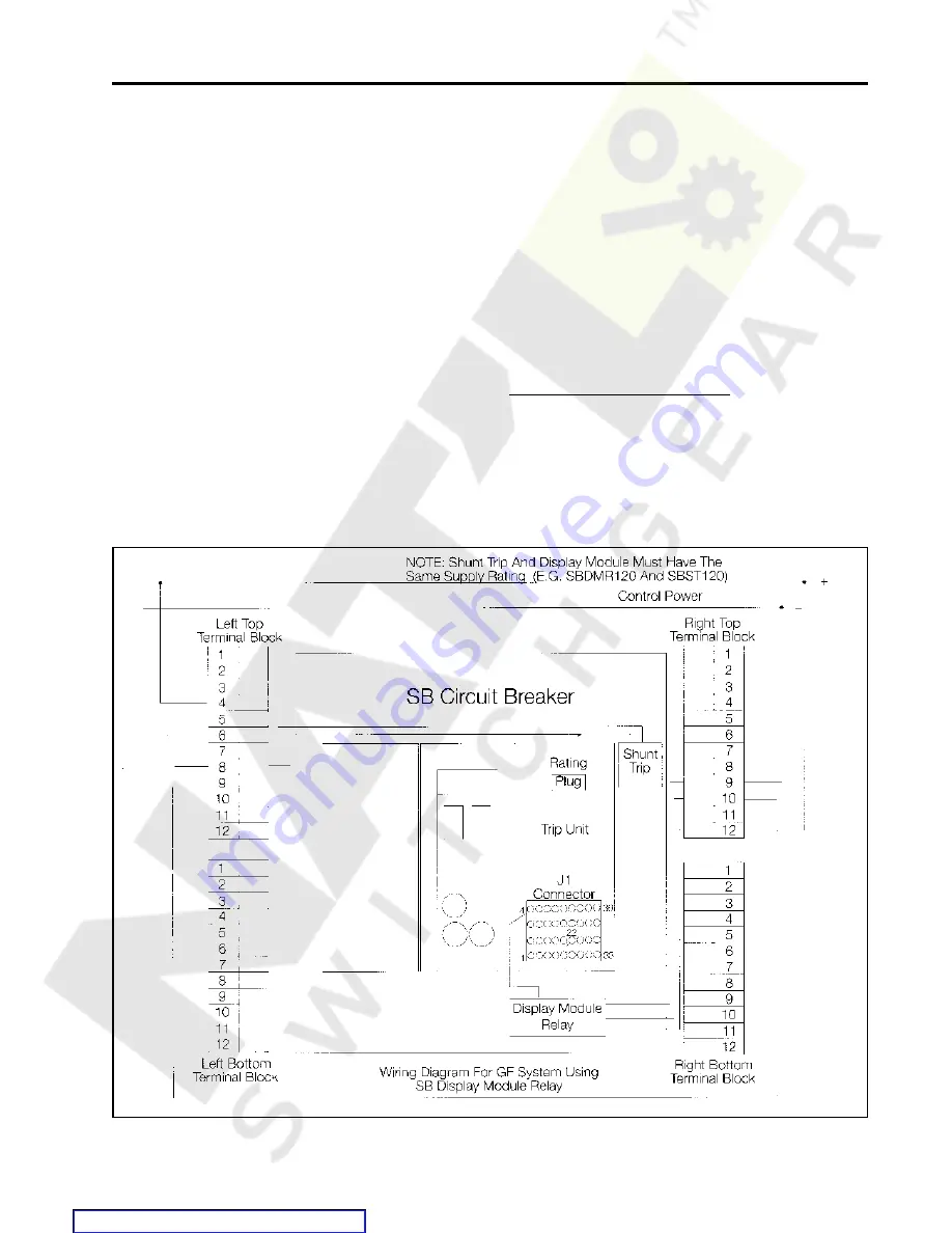
Figure 1.
Summary of Contents for SBA 1200
Page 68: ...66 External Accessories Ground Fault Sensing and Relaying Courtesy of NationalSwitchgear com ...
Page 94: ...92 Outline Dimension Drawing 2000A Fixed Mounted Courtesy of NationalSwitchgear com ...
Page 95: ...93 Outline Dimension Drawing 2000A Fixed Mounted Courtesy of NationalSwitchgear com ...
Page 100: ...98 Courtesy of NationalSwitchgear com ...
Page 101: ...Electrical Diagrams 99 Courtesy of NationalSwitchgear com ...
Page 102: ...100 Electrical Diagrams Courtesy of NationalSwitchgear com ...


