Product properties
3.27 Button
SCALANCE X-200
Operating Instructions, 12/2011, A5E00349864-19
119
3.27
Button
Button function
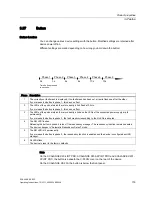
You can change various device settings with the button. Modified settings are retained after
device power off/on.
Different settings are made depending on how long you hold down the button:
3KDVH
3KDVH
3KDVH
3KDVH
3KDVH
3KDVH
7LPHEXWWRQSUHVVHG
LQVHFRQGV
V
V
V
V
V
V
Phase Description
1
The currently set fault mask is displayed. If no fault mask has been set, all ports flash one after the other.
If you release the button in phase 1, this has no effect.
2
The LEDs of the ports at which there is currently a link flash at 2.5 Hz.
If you release the button in phase 2, this has no effect.
3
The LEDs of the ports at which there is currently a link and the LEDs of the connected power supply are lit
permanently.
If you release the button in phase 3, the fault mask corresponding to the lit LEDs is adopted.
4
The RM LED flashes.
Releasing the button in phase 4 turns off the redundancy manager. The redundancy function remains enabled.
The device changes to "Automatic Redundancy Detect" mode.
5
The RM LED is lit permanently.
If you release the button in phase 5, the redundancy function is enabled and the device is configured as HSR
manager.
6
All LEDs flash.
The device is reset to the factory defaults.
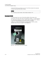
Note
On the SCALANCE X204 IRT PRO, SCALANCE X202-2P IRT PRO and SCALANCE X201-
3P IRT PRO, the button is beneath the C-PLUG cover on the rear of the device.
On the SCALANCE XF-200, the button is below the front panel.
Summary of Contents for SCALANCE X-200
Page 12: ...Table of contents SCALANCE X 200 12 Operating Instructions 12 2011 A5E00349864 19 ...
Page 284: ...Technical specifications SCALANCE X 200 284 Operating Instructions 12 2011 A5E00349864 19 ...
Page 288: ...References SCALANCE X 200 288 Operating Instructions 12 2011 A5E00349864 19 ...
Page 294: ...Dimension drawings SCALANCE X 200 294 Operating Instructions 12 2011 A5E00349864 19 ...


