4
Installation and Testing
4.7.3
Time Overcurrent Pickup Test
(Continued)
Verify time overcurrent pickup as follows:
1 . After performing the above preliminary steps, connect the
input current source to terminals 7 and 8 on the relay case
(Phase A).
2. Set the PHASE TAP switch to position A.
3. Adjust the input current source to 1 1
0%
of the value shown
on the front panel table for TAP A {HIGH or LOW range as
indicated by the second digit of the style number). Observe
that the PHASE A TMG LED illuminates.
4. Adjust the current source so that the PHASE A TMG LED
goes dark. The current applied when the LED extinguishes
should be between the pickup point (from the table) and
.
9
0
times the pickup point.
5.
Repeat steps 3 and 4 with the PHASE TAP switch set to B,
C, D, E, F, G, H, I, and J successively.
NOTE
If this is a single-phase relay, this completes the Time
Overcurrent Pickup Test. If this is a three-phase relay,
perform steps 6, 7, 8, and 9 below. If two-phase-with
ground relay, perform steps 6, 7,
1 0,
and 1 1 below. If
three-phase-with-ground, perform all of the following
steps.
6. Disconnect the input current source from terminals 7 and
8 (Phase A) and connect
it
to terminals 1 4 and
1 5
(Phase
B).
7. Repeat steps 2 through 5 above for Phase B.
8. Disconnect the input current source from terminals 1 4 and
1 5
(Phase B) and connect it to terminals 1 7 and 1 8 (Phase
C).
9 . Repeat steps 2 through 5 above for Phase C .
1
0.
Disconnect the input current source from terminals 1 7 and
1 8 (Phase C) and connect it to terminals 1 3 and 1 6
(Ground).
1 1 . Repeat steps
2
through 5 above for ground current.
Page
22
BUS
A
B
c
52
51
51
A
8
51
B
51
14
1 5
51
c
51
18
51
N
51
13
16
-
LEGEND
A
B
C
LINE
51
52
OVERCURRENT RELAY
POWER CIRCUIT BREAKER
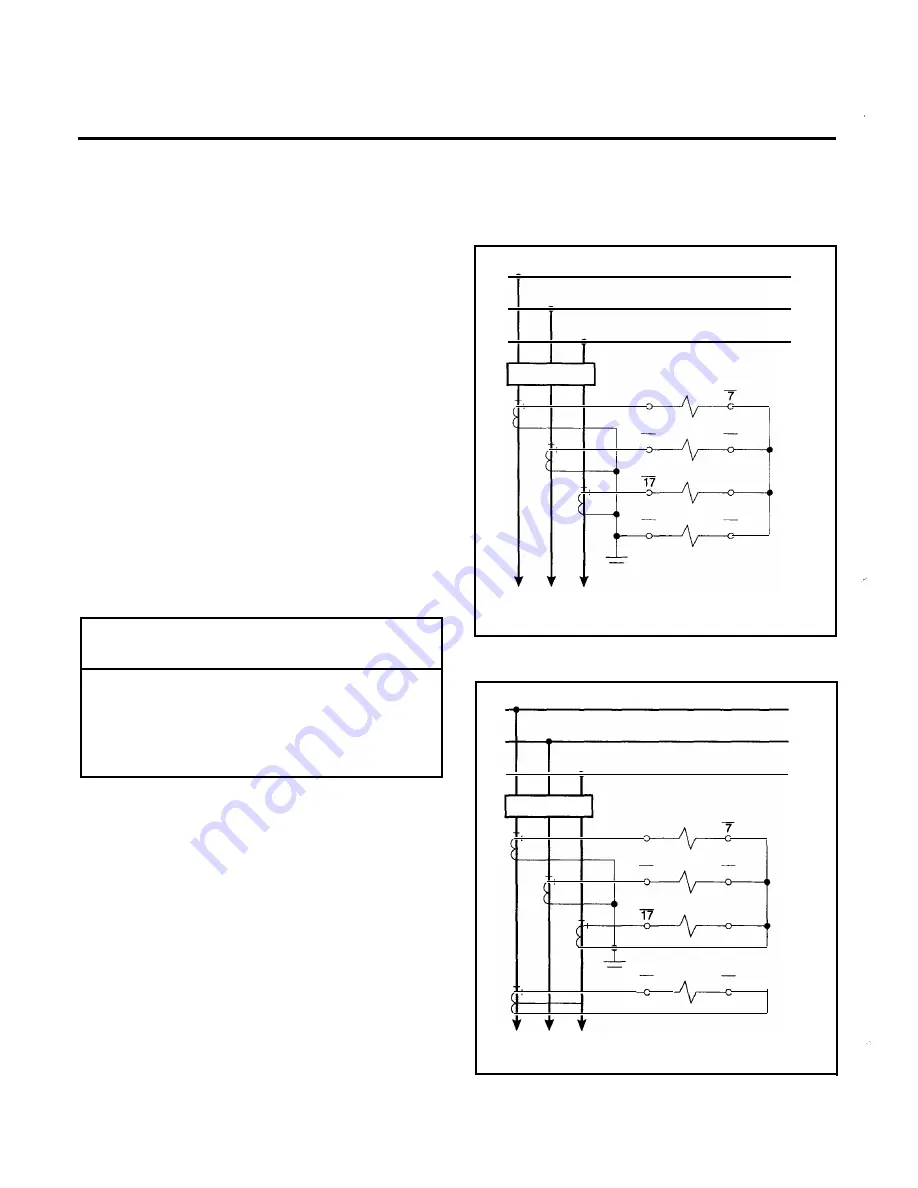
Figure 10.
Three-Phase with Residually Connected
Ground, Current Sensing Connections
BUS
52
A
B
C
LINE
A
B
c
51
51
8
A
51
B
51
14
1 5
5 1
c
51
18
-
51
G
51
13
1 6
LEGEND
51
52
OVERCURRENT RELAY
POWER CIRCUIT BREAKER
Figure 1 1 .
Three-Phase with Independent Ground,
Current Sensing Connections
www
. ElectricalPartManuals
. com


