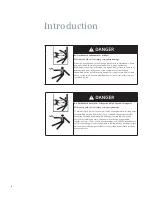
background image

15

Instrument 
transformers

Current transformers (CTs)

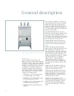
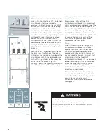
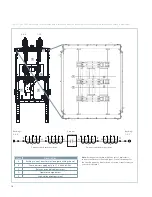
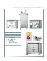
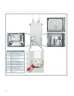
Figure 5: Type SDV7 distribution circuit 
breaker with interphase barriers and 
bushing current transformers installed in 
primary compartment on page 16 illustrates 
bushing (toroidal) CTs installed in the 
primary compartment of a type SDV7 
distribution circuit breaker. The roof 
bushings pass through the CTs. Up to two 
CTs may be mounted around each roof 
bushing. The bushing CT connections are 
wired to separate terminal blocks located in 
the low-voltage operator compartment. 
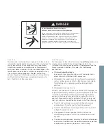
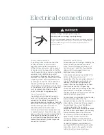
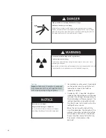
Hazardous voltages.

Will cause death, serious injury or property damage.

Do not operate current transformers with the secondary open circuited. 
Current transformers must be either connected to a load or short circuited. 
Current transformer secondary circuits also must be grounded.

Phase barriers

Phase barriers are provided on all 27.6 kV 
and 38 kV class type SDV7 distribution 
circuit breakers as shown in Type SDV7 
distribution circuit breaker with interphase 
barriers and bushing current transformers 
installed in primary compartment on page 
16. These plates of insulating material are 
attached to the circuit breaker housing and 
provide suitable electrical insulation 
between the vacuum interrupter primary 
circuits. 

Summary of Contents for SDV7

Page 1: ...Instruction manual Type SDV7 non arc resistant distribution circuit breaker Installation operation maintenance E50001 F710 K377 V6 4A00 www usa siemens com sdv7 ...

Page 2: ...rst aid Further a qualified person shall also be familiar with the proper use of special precautionary techniques personal protective equipment insulation and shielding materials and insulated tools and test equipment Such persons are permitted to work within limited approach of exposed live parts operative at 50 volts or more and shall at a minimum be additionally trained in all of the following ...

Page 3: ...elationship The sales contract contains the entire obligation of Siemens Industry Inc The warranty contained in the contract between the parties is the sole warranty of Siemens Industry Inc Any statements contained herein do not create new warranties or modify the existing warranty Table of contents Introduction 04 05 General description 06 07 Receiving handling and storage 08 10 Installation 11 1...

Page 4: ...ing procedures applicable to the installation Use appropriate personal protective equipment PPE for the voltage and arc flash incident energy exposure Arc flash hazard and hazardous voltages Will cause death serious injury or property damage Always de energize and ground the equipment before maintenance Read and understand this instruction manual before using equipment Maintenance should be perfor...

Page 5: ...t the nearest Siemens representative if any additional information is desired Signal words The signal words danger warning and caution used in this manual indicate the degree of hazard that may be encountered by the user These words are defined as Danger Indicates an imminently hazardous situation that if not avoided will result in death or serious injury Warning Indicates a potentially hazardous ...

Page 6: ...s of variations that may be encountered in connection with the installation operation and maintenance of this equipment Should additional information be desired including replacement instruction manuals contact your local Siemens representative Scope These instructions cover the installation operation and maintenance of Siemens type SDV7 distribution circuit breaker using vacuum interrupters The e...

Page 7: ... F710 K378 X XXXX for instructions applicable to the type 3AH35 MA magnetic actuator operator General description The distribution circuit breaker described in this instruction manual is of the ac high voltage outdoor circuit breaker type as defined in ANSI IEEE C37 and NEMA SG4 standards All high voltage parts excluding roof bushings are completely enclosed within grounded barriers The secondary ...

Page 8: ...elivery receipt can determine the outcome of any damage claim to be filed Notification to carrier within 15 days for concealed damage is essential if loss resulting from unsettled claims is to be eliminated or minimized Receiving handling and storage 1 When shipment arrives note whether equipment is properly protected from the elements Note trailer number on which the equipment arrived Note blocki...

Page 9: ... and forward it along with a copy of the noted delivery receipt to Siemens at 1 800 347 6659 or 1 919 365 2200 outside the U S Approval must be obtained by Siemens from the carrier before any repair work can be performed Before approval can be obtained Siemens must have the above referenced documents The carrier inspection report and or driver s signature on the delivery receipt does not constitut...

Page 10: ...on the top of the type SDV7 distribution circuit breaker as illustrated in Figure 2 Lifting type SDV7 distribution circuit breaker with crane A crane with sufficient height should be used so the load angle on the lifting cable will be approximately 60 when viewed from the front or rear Storage When it is necessary to store a type SDV7 distribution circuit breaker in an area exposed to the weather ...

Page 11: ... and install the legs at the desired height Installation The legs must be installed and turned inward so that the two sides of the each leg are adjacent to the enclosure sides and the hole at the bottom of the leg is inside the perimeter of the enclosure as in Figure 3 Outline drawing on page 12 Use anti seize compound Loctite 77164 or 77124 nickel anti seize on the 1 2 13 SAE stainless steel cap ...

Page 12: ...1 321 63 1 1 603 Q 31 3 795 39 4 1 001 39 4 1 001 50 9 1 293 G 44 5 1 130 57 8 1 468 49 6 1 260 63 2 1 605 R 38 8 986 47 0 1 194 46 8 1 189 58 4 1 483 H 8 0 203 18 4 467 11 5 292 20 4 518 S 4 0 102 28 0 711 4 0 102 28 0 711 4 0 102 28 0 711 4 0 102 28 0 711 I 19 8 503 21 0 307 21 0 307 22 2 564 T 73 5 1 867 77 2 1 961 77 6 1 971 93 5 2 375 J 8 0 203 18 4 467 11 5 292 20 4 518 U 92 0 2 337 116 0 2 ...

Page 13: ... 321 63 1 1 603 C 6 0 152 6 0 152 6 0 152 6 0 152 D 12 0 305 12 0 305 12 0 305 12 0 305 E 21 3 541 26 0 660 26 0 660 31 5 800 F 4 9 124 3 9 99 4 9 124 5 1 130 G 31 3 795 39 4 1 001 39 4 1 001 50 7 1 288 H 36 1 917 44 2 1 123 44 2 1 123 55 6 1 412 I Outer door 40 0 1 016 46 5 1 181 46 5 1 181 46 8 1 189 J Inner relay panel when supplied 36 0 914 42 8 1 087 42 8 1 087 41 3 1 049 Dimensions in inches...

Page 14: ...ions in a similar manner Check that the protective relay panel if so equipped clears any additional wiring installed A conduit panel opening is provided in the bottom of the relay and control compartment for the connection of control circuits The control wires should be run separately from high voltage wiring to prevent inductive coupling between them and should be sized for full operating current...

Page 15: ...ment Hazardous voltages Will cause death serious injury or property damage Do not operate current transformers with the secondary open circuited Current transformers must be either connected to a load or short circuited Current transformer secondary circuits also must be grounded Phase barriers Phase barriers are provided on all 27 6 kV and 38 kV class type SDV7 distribution circuit breakers as sh...

Page 16: ... kV C Relay and control compartment D Operator compartment E High voltage compartment X1 X2 X3 X4 X5 X1 X2 X3 X4 X5 X5 X4 X3 X2 X1 X5 X4 X3 X2 X1 X X Y Y Bushings 2 4 6 Bushings 1 3 5 Vacuum interrupter Current transformer positions Current transformer positions Note Arrangement shown with four sets of multi ratio current transformers five lead type Consult drawings for the specific quantity and l...

Page 17: ...ocess it is critical to first verify that the control power is de energized the spring loaded mechanisms are in the discharged condition and the circuit breaker main contacts are open De energizing control power in a power circuit breaker To de energize the control power open the disconnect device in the relay and control compartment Figure 6 Relay and control and operator compartments for type SD...

Page 18: ...erator compartments for type SDV7 SE circuit breaker with stored energy operator on page 19 1 De energize control power 2 Press red open button on the operating mechanism 3 Press black close button on the operating mechanism 4 Again press red open button on the operating mechanism 5 Verify spring condition indicator shows DISCHARGED 6 Verify main contact status indicator shows OPEN Physical inspec...

Page 19: ...ription A External manual trip B Control disconnect device C Relay and control compartment D Operator compartment E Push to trip pushbutton F Push to close pushbutton G Operations counter H OPEN CLOSE indicator I CHARGED DISCHARGED indicator J Opening for manual charging K Reset mechanism for external manual trip C D A B H I E F J G A K C ...

Page 20: ...rging to take place 1 Use the manual close and open controls refer to Figure 6 Relay and control and operator compartments for type SDV7 SE circuit breaker with stored energy operator on page 19 to first close and then open the circuit breaker contacts Verify contact positions visually by observing the OPEN CLOSED indicator on the circuit breaker 2 Open control power circuit by opening knife switc...

Page 21: ...erating mechanism has been properly lubricated 5 Blocking supports and other temporary ties remove from circuit breakers instruments protective relays etc 6 Proper fuses correctly placed 7 Temporary wiring jumpers used on the secondaries of current transformers wired to external devices as shown on wiring diagrams removed 8 Ground connections properly made 9 Incoming primary and secondary connecti...

Page 22: ...with closed contacts or with open contacts with rated operating voltage applied High potential tests employ hazardous voltages Will cause death or serious injury Follow safe procedures exclude unnecessary personnel and use safety barriers Keep away from circuit breaker during application of test voltages After test completion ground both ends and the middle ring if visible of the vacuum interrupte...

Page 23: ...25 volts ac or 1 590 volts dc The above voltages are in accordance with NEMA Standards Note Certain control devices such as motors and motor circuits should be tested at 675 volts ac Electronic devices should be tested at the voltages specified in the instruction manual for the electronic device 3 Charge the closing springs manually and push the close pushbutton to close the circuit breaker 4 Veri...

Page 24: ...t breaker Torque should be in the range of 20 25 ft lbs 27 34 Nm 3 Connect primary incoming power source to circuit breaker 4 Check all instruments protective relays meters etc 5 Connect as small a load as possible and observe instruments 6 Gradually connect more load to the equipment while observing instruments until the full load is connected 7 Check for signs of overheating of primary and secon...

Page 25: ...cts are open Hazardous voltages and high speed moving parts Will cause death serious injury or property damage Read instruction manuals observe safety instructions and use qualified personnel De energizing control power in a power circuit breaker To de energize the control power open the disconnect device in the relay and control compartment Figure 8 Relay and control and operator compartments for...

Page 26: ...6 1 105 2 106 2 106 4 106 3 105 2 105 5 NOTICE Capacitor discharge plug 105 2 Disconnect control power prior to removing or replacing the capacitor discharge plug Refer to Figure 7 To discharge capacitors Disconnect control power to the circuit breaker by opening the disconnect device device 08 in the typical schematic in Figure 10 on page 51 located in the control compartment After control power ...

Page 27: ...and control circuits have been de energized for a long time the power supply capacitors will maintain significant stored energy Always discharge the capacitors before maintenance Always de energize and ground the equipment before maintenance Read and understand this instruction manual before using equipment Maintenance should be performed only by qualified personnel The use of unauthorized parts i...

Page 28: ...controls and discharging capacitors on page 26 to first close and then open the circuit breaker contacts Verify contact positions visually by observing the OPEN CLOSED indicator on the circuit breaker 3 In step 2 when the close pushbutton was pressed the circuit breaker should have closed and the capacitors should have recharged automatically Upon closing the yellow LED should be on followed by th...

Page 29: ...pacitors on page 26 to close the circuit breaker 3 Use the manual opening handle on the right side of the enclosure refer to Figure 8 Relay and control and operator compartments for type SDV7 MA circuit breaker with magnetic actuator operator on page 30 to open the circuit breaker 4 Attempt to close the circuit breaker using the pushbutton on the circuit breaker operating mechanism refer to Figure...

Page 30: ...partment open D Operator compartment E Push to trip pushbutton F Push to close pushbutton G Operations counter H OPEN CLOSE indicator I Reset mechanism for external manual trip Figure 8 Relay and control and operator compartments for type SDV7 MA AR circuit breaker with magnetic actuator operator A 2 4 6 1 3 5 C2 D B H H E F G C1 I A I ...

Page 31: ...on wiring diagrams removed 8 Ground connections properly made 9 Incoming primary and secondary connections properly made and checked for shorts or undesired grounds 10 Verify all covers and bolted connectors are securely fastened 11 Protective relays coordinated with other protective relays and protection devices on the system Refer to protective relay instructions before making any adjustments 12...

Page 32: ...ion is produced with closed contacts or with open contacts with rated operating voltage applied Excessive test voltages May result in damage to equipment Do not perform dielectric tests at test voltages exceeding the ratings of the tested equipment NOTICE 1 An insulation resistance test is advisable on the control circuit to verify that all connections made in the field are properly insulated 2 A ...

Page 33: ... test It is not expected that equipment shall be subjected to these tests after it has been stored for long periods of time or has accumulated a large amount of dust moisture or other contaminants without being first restored to good condition A dielectric test on secondary and control circuits should be made for one minute at 1 125 volts ac or 1 590 volts dc The above voltages are in accordance w...

Page 34: ...t breaker Torque should be in the range of 20 25 ft lbs 27 34 Nm 3 Connect primary incoming power source to circuit breaker 4 Check all instruments protective relays meters etc 5 Connect as small a load as possible and observe instruments 6 Gradually connect more load to the equipment while observing instruments until the full load is connected 7 Check for signs of overheating of primary and secon...

Page 35: ...erience with the equipment in the actual service environment Regardless of the length of the maintenance and lubrication interval Siemens recommends that circuit breakers should be inspected and exercised annually For the safety of maintenance personnel as well as others who might be exposed to hazards associated with maintenance activities the safety related work practices of NFPA 70E especially ...

Page 36: ... fasteners are used in most other locations This list of hand tools describes those normally used in disassembly and re assembly procedures SAE U S customary Socket and open end wrenches 5 16 3 8 7 16 1 2 9 16 11 16 3 4 and 7 8 inches 7 10 13 17 and 19 mm Hex keys 3 16 and 1 4 inches 8 mm Screwdrivers 0 032 x 1 4 inches wide and 0 055 x 7 16 inches wide Pliers Light hammer Dental mirror Flashlight...

Page 37: ...ning or major repair but should be designed to reveal if possible the need for such actions in time to prevent malfunctions during operation Inspection items and tests Primary power path checks Cleanliness check Inspection of flexible connectors Magnetic actuator operator mechanism checks Maintenance and lubrication Fastener check Capacitor charging check Contact erosion check Stored energy operat...

Page 38: ...e 7 Operator controls and discharging capacitors on page 26 1 Press red Open pushbutton 54 0 2 Remove the mechanism housing cover sheet 60 1 NOTICE Capacitor discharge plug 105 2 Disconnect control power prior to removing or replacing the capacitor discharge plug Refer to Figure 7 on page 26 To discharge capacitors Disconnect control power to the circuit breaker by opening the disconnect device de...

Page 39: ...low the recommendation that these tests contact erosion manual spring charging check and vacuum integrity high potential tests will be combined as described Cleanliness check Figure 9 is a side view of the type SDV7 distribution circuit breaker showing the vacuum interrupter bus connections and roof bushings All of these components must be cleaned and free of dirt or any foreign objects Use a dry ...

Page 40: ...e vacuum interrupter These include the standoff insulators and the insulated drive links as well as the insulating tension struts between the vacuum interrupter polehead supports If these insulation components are contaminated or defective the test voltage will not be sustained If so clean or replace the affected components and retest If dc high potential tests are used note the following If a dc ...

Page 41: ...ing charging motor 10 Perform contact resistance tests of the primary contacts using a micro ohmmeter Contact resistance should not exceed the values listed in Table 6 Maximum contact resistance micro ohms The contact resistance is measure across the phase terminals outside terminals of roof bushings 11 Make a permanent record of all tests performed Inspection and cleaning of circuit breaker insul...

Page 42: ...s are checked again for tightness and condition before placing the type SDV7 distribution circuit breaker back in service NOTICE Protective relays and instruments The type SDV7 distribution circuit breaker can be equipped with a protective relay panel when required A protective relay package can be supplied on a hinged panel mounted in the front of the relay and control compartment To ensure satis...

Page 43: ...el with a guide to identifying and correcting possible malfunctions of the type SDV7 distribution circuit breaker Circuit breaker overhaul Table 7 lists the recommended overhaul schedule for type SDV7 distribution circuit breakers operating under ANSI IEEE usual service conditions When actual operation conditions are more severe overhaul periods should occur more frequently The operations counter ...

Page 44: ...manual tripping Lubrication 1 Evidence of excessive wear 2 Lubrication of wear points Electrical controls Wiring 1 Mechanical damage or abrasion Terminals and connectors 1 Tightness and absence of mechanical damage Close and trip solenoids anti pump relay and auxiliary switches 1 Automatic charging 2 Close and trip with control power High potential test Primary circuit to ground and between primar...

Page 45: ...harge but circuit breaker does not close Closing coil or solenoid 52SRC fails to energize No sound of circuit breaker closing 1 Secondary control circuit de energized or control circuit fuses blown Correct as indicated 2 No closing signal to multi pin plug pin A2 or contacts A2 and B3 are not engaging Check for continuity and correct protective relay logic Replace contacts if required 3 Failure of...

Page 46: ...plug contacts C2 or D2 are not engaging Check and replace if required 5 Failure of trip coil 52T Check and replace if necessary 6 Auxiliary switch 52a NO contacts 23 to 24 or 33 to 34 are open when circuit breaker is closed Check linkage and switch Replace or adjust as necessary Stored energy tripping coil 52T energizes No tripping sound is heard and circuit breaker contacts do not open In other w...

Page 47: ...le the circuit breaker can be identified by the serial number alone all additional information that is given will serve as a check to be certain that the part or parts furnished are correct for the circuit breaker in question Without this serial number Siemens cannot be sure of the correct identity of the desired parts If any doubt exists as to the instruction book reference number or the descript...

Page 48: ... 27 6 150 194 60 20 50 3 1 200 2 000 52 1 45 2 52 27 6 25 27 6 150 194 60 25 50 3 1 200 2 000 52 1 45 2 65 38 0 20 38 0 200 258 80 20 50 3 1 200 2 000 71 7 59 2 52 38 0 25 38 0 200 258 80 25 50 3 1 200 2 000 71 7 59 2 65 38 0 31 5 38 0 200 258 80 31 5 50 3 1 200 2 000 2 500 71 7 59 2 82 38 0 40 38 0 200 258 80 40 50 3 1 200 2 000 2 500 71 7 59 2 104 Footnotes 1 Standard 50 ms 3 cycle with 48 Vdc 1...

Page 49: ... 7 4 4 8 4 10 250 Vdc 180 280 140 280 2 1 9 6 4 2 2 10 120 Vac 104 127 104 127 2 0 6 10 240 Vac 208 254 208 254 2 0 3 10 Magnetic actuator operator Electronic controller power supply Input voltage range Input power Controller output Capacitor voltage2 3 4 Close Open 28 56 Vdc 80 W5 40 55 A 10 15 A 160 Vdc 95 250 Vdc 100 254 Vac 60 W 60 VA5 40 55 A 10 15 A 160 Vdc Binary inputs close and open comma...

Page 50: ... 403 Operating mechanism Stored energy magnetic actuator Stored energy magnetic actuator Stored energy magnetic actuator Closing time4 ms 65 55 65 55 70 Opening time by interrupting time4 Three cycle Five cycle ms 38 33 56 38 33 56 38 56 Dual trip coils mechanically and electrically independent Optional stored energy Optional stored energy Optional stored energy Auxiliary voltages options Close tr...

Page 51: ... 52T Opening spring release coil 52Y Anti pump relay 69 Closing cutout switch 88 Spring charge motor G Green indicating light remote R Red indicating light remote LS3 Closing spring position switch closed when closing spring is discharged LS9 Closing spring position switch open when closing spring is discharged LS21 Motor cutoff switch closed when closing spring is discharged LS22 Motor cutoff swi...

Page 52: ...dc 3 Separate close trip input power required when high range electronic controller power supply specified and low range binary input commands ST9 1 ST9 2 and ST9 4 ST9 5 Low range binary input commands requires 17 Vac or 17 Vdc 4 Schematics are shown with circuit breaker open Legend 01 C Control switch close remote 01 T Control switch trip remote 08 Power disconnect 08C T Close open power disconn...

Page 53: ... O Circuit breaker OPEN N O Common 160 Vdc 160 Vdc Ground Ground Discharge Discharge Coil Sense coil Magnetic actuator OPEN CLOSED Mechanical lockout Magnetic actuator coil Unused Magnetic actuator coil OPEN position switch CLOSED position switch 24 Vdc 24 Vdc Unused OPEN pushbutton CLOSE pushbutton Sense coil Sense coil CLOSE command CLOSE command OPEN command OPEN command Unused Power supply ...

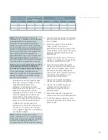
Page 54: ...54 Table 16 Remarks ...

Page 55: ...55 Table 16 Remarks continued ...

Page 56: ...rther development of the products The requested performance features are binding only when they are expressly agreed upon in the concluded contract Article No E50001 F710 K377 V6 4A00 Printed in U S A 2016 Siemens Industry Inc Published by Siemens Industry Inc 2015 Siemens Industry Inc 7000 Siemens Road Wendell North Carolina 27591 For more information please contact our Customer Support Center Ph...

Reviews: