background image


815_58300000003806_ara_en_e.doc – 30.01.12 

Seite 38 von 67 

6.3 

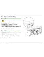
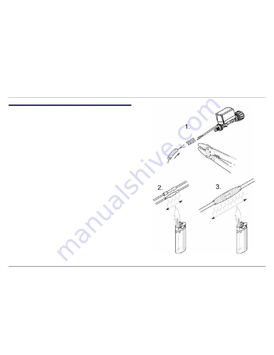
Replacing the Aqua Stop valve 


Open the housing 


Disconnect the inlet hose 


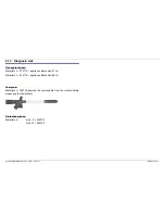
Cut through the electric connecting cables 


Strip the insulation off the cable ends 


Push the shrink-fit hose over the cable 


Connect electric cables to the insulating sleeves (1.) 


After fitting, warm the connectors until the shrinkage process occurs 
and the hot-melt adhesive comes out of the ends of the connectors 
(2). 


Push the shrink-fit hose over the connectors and also warm until 
the shrinkage process is complete (3) 


Summary of Contents for SE25M575GB series

Page 1: ...18 4 9 Optical low rinse aid sensor optional 19 4 10 Dispenser 20 4 11 Instantaneous water heater 21 4 12 Water softening system 22 4 13 Detergent solution pump 23 4 14 Level sensor with safety function 24 4 15 Filter system 25 4 16 Spray system 26 4 17 Rinsing and pumping system 27 4 18 Door spring 28 4 19 Circulation pump SICASYM 29 4 20 Water inlet with heat exchanger 30 4 21 Water points optio...

Page 2: ...AGNOSTICS 50 7 1 Controller module 50 7 2 Mechanical faults 51 7 3 Draining 52 7 4 Odour 53 7 5 Noises 54 7 6 Rinsing result 55 7 7 Drying result 64 7 8 Circulation pump 65 8 TECHNICAL SPECIFICATIONS 66 8 1 General technical specifications 66 8 2 Consumption rates 67 ...

Page 3: ...safety and appliance function When repairs are complete conduct a test in accordance with VDE 0701 or the corresponding national regulations When repairs are complete perform a function and leak test WARNING Comply with the following instructions If conducting the test in accordance with VDE 0701 via the connector the heater instantaneous water heater must be tested directly for insulation faults ...

Page 4: ...es which are fitted to the end built in or under or are free standing 2 2 Electrical connection Connect the appliance to a correctly installed earthed socket only Comply with the specifications on the rating plate 2 3 Water connection If the appliance is connected to the drain with the standard hose length the max permitted height from the floor is 90 cm If the drainage hose is extended a max heig...

Page 5: ... TP The timer programming button enables the start time to be delayed by up to 24 h 3 3 2 Soaking optional The soaking button can also be selected for any rinse programme If the button is pressed an additional prerinse occurs and the bottom basket is heated to 55 This causes the running time to be extended by approx 20 min Recommended for mixed utensils top basket fragile utensils bottom basket ve...

Page 6: ...e but it also specifies the temperature of the wash cycle and the number of intermediate rinse cycles If clean water is detected in the prerinse the water from the prerinse is also used in the wash cycle a wash cycle at 65 one intermediate rinse cycle and a drying cycle If dirty water is detected in the prerinse the prerinse cycle runs a wash cycle at 51 two intermediate rinse cycles and a drying ...

Page 7: ...nd switch on the appliance S 00 is indicated on the digital display If the S4 button is pressed again S 01 is displayed and intensive drying is switched on When the appliance is switched off the value is saved If intensive drying is activated the temperature is in creased by 3 K in the final rinse to improve the drying result 3 5 3 De activating the low rinse aid indicator Hold down the S0 button ...

Page 8: ...e Hold down S5 button for at least 4 sec CL is displayed If a button is pressed while the programme is running CL is displayed The programme cannot be reset Deactivation Hold down S5 button for at least 4 sec until CL goes out When the programme ends the button lock is deactivated If there is a power failure the button lock is activated Whenever a programme is started the button lock must be re ac...

Page 9: ... the filling position the filler valve is actuated until the safety level is reached The safety switch switches the detergent solution pump on and switches the filler valve off When the safety switch has switched back the filler valve is re actuated This results in a switchover between pumping and filling If the level switch f1 does not switch over within 6 min the pro gramme is terminated 1 min p...

Page 10: ...e the inherent heat of the dishes The heat exchanger is not filled 4 1 4 Memory electronics The electronics module has its own memory which remembers the programme last selected If no new selection is made at the start of the programme the programme last selected will run 4 1 5 Power failure The electronics module has a power failure memory function which ensures that the current rinse programme c...

Page 11: ... service test programme Before replacing a module follow the ESD instruc tions Before replacing a module due to a defective triac test the actuated component A Heat exchanger outlet valve E Circulation pump B Regeneration valve F Raw water valve C Filler valve G Dispenser actuator D Water points H Switch controller power supply unit ...

Page 12: ...1 9 Initial start up Replacing the electronics The following programme sequence must be taken into consideration during the initial start up or when replacing the electronics Programme counter 0 Programme sequence during the initial start up with heat exchanger ...

Page 13: ...TC 1 the PTC heats up and transfers the heat to the wax filled metal cylinder 4 The wax expands and forces the plunger 6 out of the cylinder The plunger 6 transfers the mechanical movement to the release mechanism for dispensing the detergent and rinse aid If the heat source is switched off the volume of wax is reduced by the cooling process The pressure spring 3 returns the plunger 6 back to its ...

Page 14: ...ht emitted by the infrared diode can no longer reach the photodiode The absent voltage signal is detected by the microcomputer Depending on the programme type the water is changed after the prerinse or even the washing temperature is changed If the turbidity value is not reached the water remains in the rinsing tank for the wash cycle In each programme sequence in which the Aqua sensor is active t...

Page 15: ...he base pan The Aqua Stop valve is enclosed by a housing The housing is connected to the bottom pan by a leakage water hose sleeve of the inlet hose D The inlet hose C and the electric control cable B for the solenoid valve are situated in the leakage water hose D If leaks occur in the area of the valve or inlet hose these are conveyed into the base pan via the leakage water hose 4 4 2 Technical s...

Page 16: ...ised temperature safety switch 85 C is combined with the NTC sensor If a fault occurs the heater is switched off at a water temperature of 85 C operates in switching mode Temperature in C Resistance in kW Tolerance C 25 48 4 7 9 30 38 5 7 1 50 16 5 6 2 60 11 0 5 6 65 9 1 5 5 ...

Page 17: ...rear on the water softening system A and is responsible for admixing hard water The raw or soft water valve D is actuated via the electronics module which calculates how frequently and how long the valve is to be actuated for As a result a constant water hardness of approx 5 dH is obtained For this reason it is important to set the hardness range precisely If the valve is actuated open the raw wat...

Page 18: ...nal The dispenser contains a float with an integrated permanent magnet A The magnetic field actuates a reed switch on the outside of the dispenser The lamps of the refill indicators in the control panel are switched on via this reed switch A Permanent magnet B Reed switch open C Reed switch closed ...

Page 19: ... receiver diode B via a prism C If the dispenser is full the light beam in the prism is scattered The received signal is weaker than the transmitted one If the dispenser is empty the light beam in the prism is reflected The received signal is the same as the transmitted signal The module evaluates the received signal and the refill indicator LED is actuated A Transmitter diode B Receiver diode C P...

Page 20: ...ease pawl engages with the switching core B of the rinse aid lever so that when the actuator C is activated again the dosing plunger A is lifted off the rinse aid Technical specifications Value Unit Rinse aid capacity 120 ml Setting 1 6 1 each ml Detergent capacity max 45 g See Actuator for additional technical specifications A Dosing plunger D Magnetic float B Switching core E Reed contact option...

Page 21: ...e flange actuates the safety pressure switch D for the heating element C If the pressure drops the heater switches off The heating position is overtravelled preventing dry heating Technical specifications Designation Value Unit Nominal voltage 230 240 V Frequency 50 Hz Power 2150 W Resistor approx 22 Ω A Clicking safety device NTC 85 C safety switch E From the circulation pump B Membrane F To the ...

Page 22: ...in Calcium and magnesium are bonded to the surface of the exchange compound while sodium ions are released into the water Fig 1 When all sodium ions have been replaced with ions of the hardness constituents the capacity of the water softening system is exhausted and it must be regenerated 4 12 2 Regeneration To make the ion exchanger functional again a concentrated saline solution sodium chloride ...

Page 23: ...pump The detergent solution pump is flange mounted on the pump sump It pumps the detergent solution out of the appliance Technical specifications Designation Value Unit Nominal voltage 230 240 V Frequency 50 Hz Resistor approx 110 260 Ω Delivery height 0 9 m Delivery capacity 10 l m ...

Page 24: ...e water hose Once a predefined level has been reached in the base pan E the float uses a switch lever to actuate the safety level switch B which then electrically switches off the filling and safety valve At the same time the drainage pump is switched on the detergent solution is removed from the rinsing tank and the drainage pump switches to continuous operation A Level switch G Air chamber B Saf...

Page 25: ...rking in order to prevent dirt particles penetrating the rinsing circuit 3 stage filter system 4 stage filter system A Coarse filter C Microfilter cylinder B Surface filter D Fine filter cylinder A Coarse filter E Rinsing tank B Fine filter cylinder F Pump sump C Surface filter G Supply pipe to upper spray arm D Microfilter cylinder H Lower spray arm ...

Page 26: ... the instantaneous water heater situated under the pump sump D The upper spray arm F is attached by its inlet pipe directly to the top basket Connection to the supply pipe is by a variable coupling B If appliances feature a height adjustable top basket the water inlet to the spray arm is adjusted via this variable coupling The lower spray arm E is connected with its bearing assembly to the second ...

Page 27: ...e A temperature controller B connected in series disconnects the appliance at 85 C to prevent overheating In mechanically controlled appliances this temperature switch A isٔ combined with a 65 C temperature controller and housed in one module in electronically controlled appliances it is combined with an NTC sensor negative temperature coefficient and housed in one module The sensor surface is in ...

Page 28: ...ensile force of the standard installed springs and maximum pretension of the spring tensioner is no longer adequate In this case stronger door springs see table may be used If furniture doors are very light the door springs can also be replaced by lighter ones Spring force Coloured dot Material no Max weight of furniture d grey 165891 Approx 10 5 kg green 165736 black 168648 brown 167022 red 16529...

Page 29: ...e After the switchover phase the windings are then in series one behind the other i e each winding is connected to half the mains voltage The motor is then adjusted optimally to the operating pump and gene rates very little noise apart from a very low power consumption for label AAA as the windings are connected to half the mains voltage during operation The motor features a thermal winding cover ...

Page 30: ...e of completed rinse cycles is recorded by the electronics counter which determines when the water softener requires regeneration Before each regeneration step the electronics check whether the capacity of the water softener is adequate for a complete Normal Programme Sequence If not regeneration starts The water softening system is regenerated and rinsed through during the wash cycle The regenera...

Page 31: ...the normal volume of water is run in During the initial water inflow for the rinse programme this volume of water compensates for the loss of water which is used to wet the dry utensils The circulation pump is guaranteed to run true and water is saved in the subsequent filling baths The circulation pump is switched on time delayed the drainage valve remains open until the heat exchanger has emptie...

Page 32: ... the cam disc B and the locking disc C The locking disc C locks the relevant water channel to the spray arms The locking disc C has two openings which differ in size The smaller opening reduces the flow rate to the top basket The controller receives information on the position of the locking disc C from the microswitch A which is actuated by the cam disc B The water points are integrated in the in...

Page 33: ...ing cycle with the saved water for subsequent drying support The special programme sequence is activated if the electronics module detects low rinse aid the rinse aid refill indicator is deactivated The Intensive drying additional function can still be selected but it has no effect on the rinse aid temperature The maximum temperature increase is 3 K 5 1 2 Application area 3 in 1 detergents have an...

Page 34: ...n 67 6 REPAIR 6 1 Module 6 1 1 Removal Remove the furniture front if fitted Remove outer door Disconnect support plate with the fascia from the inner door Disengage four catches on the fascia from the support plate Tilt support plate away from the fascia ...

Page 35: ...rom the module plugs are coded 6 1 2 Installation Connect plugs from the cable harness to the module Push module into the control panel frame until the module is held firmly in place by the catches Attach support plate to the inner door Attach fascia from above into the support plate and tilt down until the four catches lock Attach outer door Attach furniture front if fitted ...

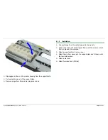
Page 36: ...isplay foil 6 2 1 Removal 1 Slightly raise the catch for the display foil 2 Push display foil to the right and remove 6 2 2 Installation 3 Insert display foil into the lower guide When pushing in the display foil ensure that it is inserted at the top in all guides ...

Page 37: ...815_58300000003806_ara_en_e doc 30 01 12 Seite 37 von 67 4 Push display foil to the left into the holder until it locks ...

Page 38: ...bles Strip the insulation off the cable ends Push the shrink fit hose over the cable Connect electric cables to the insulating sleeves 1 After fitting warm the connectors until the shrinkage process occurs and the hot melt adhesive comes out of the ends of the connectors 2 Push the shrink fit hose over the connectors and also warm until the shrinkage process is complete 3 ...

Page 39: ...optional 6 4 1 Removal Catch tappets are located on the rear right and left hand sides of the worktop Press up the catch tappets Push back the worktop and lift off 6 4 2 Installation Insert worktop into the guide Push forwards until both catch tappets engage at the rear ...

Page 40: ...lates A stamped out of the inner door off the catches B Press the released dispenser inwards 6 5 2 Installation Align retention plates A towards the centre so that all catches B lock securely into position Before installing the seal lubricate with washing up liquid Press dispenser outwards into the inner door Ensure that all retention plates A are firmly attached again Attach electrical connection...

Page 41: ...osen connection between stainless steel container and plastic base pan 2 screws at front and 2 screws at rear Raise container on the right side and tilt to the left Secure container with an approx 4 cm thick object Using a screwdriver press the catch on the right side of the circulation pump inwards Rotate pump to the right Remove pump ...

Page 42: ...ft into the pump housing until the catch engages Tilt container back into base pan Screw stainless steel container to the base pan Screw on base plate and side panels 6 6 3 Removing the slide ring seal Remove circulation pump Loosen fan impeller locking the rotor with a pen or screwdriver Remove pump housing Remove slide ring seal 6 6 4 Installing the slide ring seal Sluggish or blocked fan impell...

Page 43: ... and base plate Press lever 1 to right and disengage Rotate detergent solution pump forwards 2 After a quarter revolution remove detergent solution pump to right 3 6 7 2 Installation Insert detergent solution pump Rotate detergent solution pump to rear until the locking lever engages Screw on base plate and base panel ...

Page 44: ...ng screw from the hinge plate towards the base pan as well as the adjusting screw if fitted Unscrew hinge plate A from the frame Pull up the hinge plate A and remove Remove the spring clamp D Two piece hinge bearing bush Open the bearing bush C by disengaging the spacer G with a screwdriver see sketch One piece hinge bearing bush Open the bearing bush C by bending up the clips H with a screwdriver...

Page 45: ...e hinge plate A Insert hinge plate A into the base pan Screw hinge plate A to the frame and base pan Insert hinge lever B with the bearing bush C into the hinge plate A Screw inner door to hinge lever B Attach tension cord E to the hinge lever B Screw on side panels angle strip base panel and outside door ...

Page 46: ...g the base pan until the water softening system can be removed from the plug and socket connections at the water inlet and from the level sensor housing 13 Pull out the reed switch 14 Take out water softening system 6 9 2 Installation Please note before and during installation Place the seal on the filler neck of the salt dispenser Insert sealing rings into the plug and socket connections Put rubb...

Page 47: ...onnection in the base pan 6 Place the appliance on its back carefully remove the base pan and loosen the catch between the level sensor housing and the water softening system 7 Disconnect the circulation pump with the rubber support from the base pan 8 Open the base pan until the instantaneous water heater can be screwed off the pump sump 9 Unscrew the instantaneous water heater 10 Release the cat...

Page 48: ...n ensure that the seal lip is pointing towards the middle of the rinsing tank otherwise there will be leaks in the area of the door adjust the length of the seal to the circumference of the container cut the ends of the seal at an angle 45 place the seal on the base of the container Splash proof protection for the lower corners Press in the seal evenly and without any kinks ...

Page 49: ... aids Transparent door Material no 21 4115 appliance dimension 81 cm Material no 21 4114 appliance dimension 86 cm Test prod Material no 340730 remove the components from the module before measuring the resistance Protective gloves Material no size 9 340728 size 10 340729 ...

Page 50: ...itch properly smoke traces may be visible on the module Regulator controller power supply unit charred by humidity in the module Mains plug Advise customer See Consumption rates or Alternate rinsing technology Before replacing the module always measure the connected consumers valves actuators etc Comply with safety instructions With the module also the sealing strip 298550 have to be renewed The p...

Page 51: ...pwards This reduces the gap between the base panel and outer door Base seal may be sheared off Place two washers mat no 320156 under the fastening screws for the base plate Base is tilted forwards gap increases Observe installation sequence First attach the outer door Then attach the base Otherwise when the outer door is inserted the base seal will be bent backwards and may shear off the first tim...

Page 52: ... the area of the hose connection at the water inlet to check remove both drainage hoses Pump is buzzing audibly Pump mechanically blocked blocked or damaged pump Clean pump or if required remove pump Pump is not running See also pump is buzzing or running audibly Water tap was closed when dry the heat exchanger was still empty the filling switch is waiting for level The pump is not activated Advis...

Page 53: ...high current cables must not be extended Advise customer Customer specifies the chemicals if required change product with citrus aroma or recommend aroma dispenser mat no 460742 Advise customer concerning the new aroma Advise customer Smell of chemicals Detergent or rinse aid Bonding agent of noise insulation fleece insulating mats Evaporation of electronic components or printed circuit boards Adv...

Page 54: ...er have pressure reducing valve fitted Rattling noises during the rinse cycle Spray arm is striking the utensils Advise customer utensils not arranged properly Alternating noises in the rinse programme Alternate rinse technology top basket rinsing 55 sec changeover 5 sec bottom basket rinsing 60 sec utilising water points Alternate pumping detergent solution pump and circulation pump are actuated ...

Page 55: ...ch deposits Analyse with diagnosis case 340070 iodine solution Water soluble or regeneration salt residue Analyse with diagnosis case 340070 dest water Discoloration colour residue e g tea tomato juice coffee lipstick etc analyse with diagnosis case 340070 chlorine bleach Detergent residue Analyse with diagnosis case 340070 dest water Water insoluble residue damage to utensils ...

Page 56: ...partially blocked Drainage hose kinked No detergent dosage or insufficient dosage wrong programme selected Unfavourable arrangement of the dishes etc very large pieces in the lower rack e g pots avoid holders dish racks twisted Spray arm is blocked by dishes or cutlery Advise customer sieve insert and care Clean parts if necessary refer customers to correct sieve insert Clean parts if necessary re...

Page 57: ...et valve in production period FD 7809 to FD 7811 the float of the top basket valve may stick between instantaneous water heater and pump sump Check level sensor function implement filling process Remove non return valve check valve and seat for dirt and if required clean Check circulation pump Check heating circuit according to circuit diagrams note pressure switch on the instantaneous water heate...

Page 58: ...al hardness in the wash and final rinse cycles Does not regenerate Untreated water valve does not open appliance is filled with untreated water only Adjusting hardness range Advise customer use phosphatic detergent Adjust regeneration position and conduct performance test observe drainage of regeneration dispenser Check regeneration valve carefully mechanical valve stem electrical actuation coil C...

Page 59: ...on Starch deposits on the utensils Underdosing of detergent wrong detergent Wrong programme selected too weak programme selected Appliance connected to hot water water inlet temperature too high Advise customer use enzyme detergent Advise customer select correct programme Check hot water connection setpoint lower than 60 C advise customer if required connect to cold water ...

Page 60: ...s Leaking salt dispenser cover check screw fitting regeneration dispenser is dispensing slowly Leaking regeneration valve regeneration dispenser is dispensing slowly Regeneration valve continuously actuated Initial clouding of glass can only apparently be wiped off Detergent solution carry over Combination product Advise customer eliminate leaks Check valve and or valve seat Electrical check with ...

Page 61: ...tact time of the oxidation bleach is too brief for a short running time and at low temperatures Silicate deposits only on glasses not to be removed Final rinse dosing set too high can be rinsed off with water Discoloration due to sulphur compounds in the air and in various food remnants Advise customer increase amount of detergent Use detergent containing chlorine bleach Recommend machine detergen...

Page 62: ...me Incorrect application of tablets note use in dispenser or cutlery basket Spray arm nozzles blocked filters locked Dispensing device in spray shadow large pan etc positioned at bottom left Check draining non return valve Detergent very lumpy washing effect and dissolving performance reduced Advise customer dishwasher not loaded properly Replace spring of dispensing device Advise customer Tablet ...

Page 63: ...nts surfaces with other utensils Utensils not dishwasher proof Cutlery corrosion cutlery not dishwasher proof knife knife blade steel is usually less resistant to corrosion Rust film Infection caused by corroding utensils or utensil baskets Optimise setting according to measurement Advise customer Advise customer select a low programme for glasses low temperature 50 C Advise customer do not switch...

Page 64: ...mer refer to function of the heat exchanger if required connect the appliance to cold water supply Check heating circuit according to circuit diagrams note pressure switch on the instantaneous water heater the circulation pump cannot build up adequate pressure if there is insufficient water in the appliance Advise customer quick programme is without drying cycle drying level option is too low Advi...

Page 65: ...n_e doc 30 01 12 Seite 65 von 67 7 8 Circulation pump Customer complaint Cause Remedial action Circulation pump does not start After a prolonged idle time the seal set may stick to the pump wheel The seal set must be replaced ...

Page 66: ...58300000003806_ara_en_e doc 30 01 12 Seite 66 von 67 8 TECHNICAL SPECIFICATIONS 8 1 General technical specifications Voltage frequency 230 240 V 50 Hz Connected load 2 3 kW Heat output 2 15 kW Fuse 10 13 A ...

Page 67: ...0242 at the start of the series Intensive 70 Auto 55 65 Eco 50 Gentle 40 Quick 35 Prerinse Duration in min 112 95 145 140 72 30 19 Current consumption in kWh 1 6 1 15 1 50 1 05 0 8 0 6 0 1 Water consumption in litres 21 11 19 14 15 10 4 With Aqua sensor 18 12 Intensive 70 Auto 55 65 Normal 65 Eco 50 Gentle 40 Quick 35 Prerinse Duration in min 115 95 140 140 140 75 30 19 Current consumption in kWh ...

Reviews: