background image


Further accessories 


8.4 8UD door-coupling rotary operating mechanism 

3KF switch disconnectors with fuses 
Manual, 09/2019, L1V30580914002A-01 

95


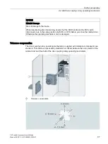
NOTICE 
Material damage 
Risk of damage to the device.  
If a force of at least 800 N pulls at the door when door interlocking is activated, the 

operating mechanism can be irreparably damaged. 


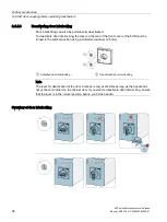
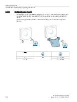
8.4.4.2


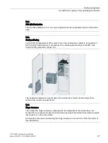
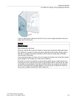
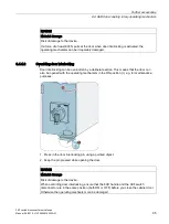
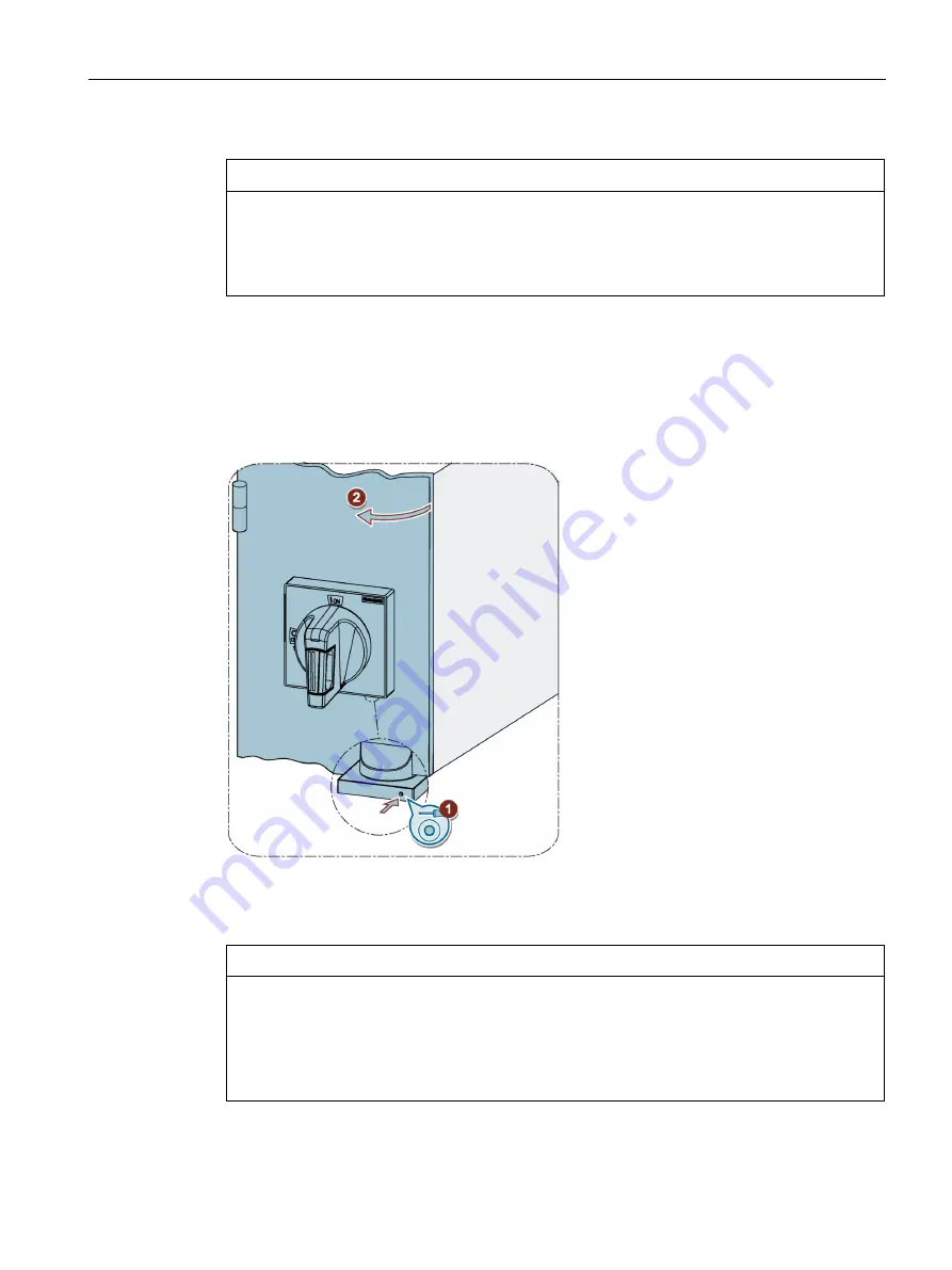
Overriding door interlocking 

Door interlocking can be overridden by a deliberate action. This means that the door can 

also be opened with the operating mechanism in the ON position (I), e.g. for maintenance 

purposes.  


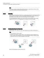
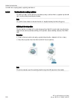
1.


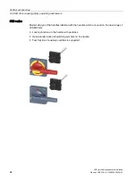
Press in the door interlocking pin using a pointed object. 

2.


Keep the pin pressed while opening the door. 


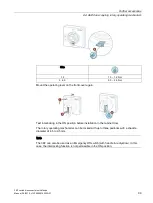
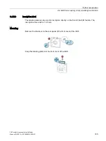
NOTICE 
Material damage 
Risk of damage to the device. 
When overriding door interlocking, ensure that the 8UD handle and the 3KF switch 

disconnector are in the same position (both ON or OFF) before you close the cabinet door. 

Otherwise the operating mechanism can be damaged. 


Summary of Contents for SENTRON 3KF LV HRC

Page 1: ...3KF switch disconnectors with fuses ...

Page 2: ......

Page 3: ...l information 2 Product description 3 Product line product group 4 Function and operation 5 Assembly and mounting 6 Connection and wiring 7 Further accessories 8 Maintenance 9 Technical specifications 10 Dimensional drawings and drilling templates 11 Appendix A ESD guidelines B List of abbreviations C Conversion tables D ...

Page 4: ...ation may be operated only by personnel qualified for the specific task in accordance with the relevant documentation in particular its warning notices and safety instructions Qualified personnel are those who based on their training and experience are capable of identifying risks and avoiding potential hazards when working with these products systems Proper use of Siemens products Note the follow...

Page 5: ... switches 22 4 2 5 Phase barriers 24 4 2 6 Cable connection covers 3KF LV HRC only 25 4 3 Exploded views 26 4 3 1 Size 1 3KF LV HRC 26 4 3 2 Size 1 3KF SITOR 27 4 3 3 Sizes 2 to 5 3KF LV HRC 28 4 3 4 Sizes 2 to 5 3KF SITOR 29 4 4 Article number structure 30 5 Function and operation 31 6 Assembly and mounting 33 6 1 Assembly of parts in the scope of supply 33 6 2 Mounting position 34 6 3 Floor moun...

Page 6: ...nals 51 7 1 4 Connection accessories 52 7 1 4 1 Phase barriers 52 7 1 4 2 Cable connection covers 3KF LV HRC only 56 7 2 Auxiliary circuit connection 57 7 2 1 Auxiliary switches 57 7 2 2 Auxiliary switches for size 1 57 7 2 3 Auxiliary switch for sizes 2 to 5 58 7 3 Contact numbers 58 7 3 1 Main circuit 59 7 3 2 Auxiliary switches 59 8 Further accessories 63 8 1 Auxiliary switches 63 8 1 1 Mountin...

Page 7: ...for 8UD 103 8 4 5 1 Shaft coupling 103 8 4 5 2 Shaft jack for sizes 1 and 2 104 8 4 5 3 Inscription label 105 9 Maintenance 107 10 Technical specifications 109 10 1 Technical specifications accessories 111 11 Dimensional drawings and drilling templates 115 11 1 Distance from grounded parts and between two 3KFs 115 11 2 Drilling templates 116 11 2 1 Drilling templates for 8UD door coupling rotary o...

Page 8: ...Table of contents 3KF switch disconnectors with fuses 6 Manual 09 2019 L1V30580914002A 01 ...

Page 9: ...n Commissioning Target group Planners installation personnel configuring engineers Required basic knowledge To understand this manual you will need to have a general knowledge of low voltage controls and power distribution Symbols used The following table explains the meaning of the various symbols used in this document Symbol Meaning Symbol Meaning Diagonal cutter File Allen key Touch operation P...

Page 10: ...g Phillips screwdriver PH Stranded conductor Slotted screwdriver Finely stranded conductor with end sleeves Trash bin Busbar Cut off in the trash bin Strip busbar OK Strip solid conductor Not OK Strip solid conductor with end sleeves Measure Strip solid conductor with end sleeves without insulating collar Handsaw ...

Page 11: ...protect against overload and short circuits in low voltage circuits as main switches EMERGENCY STOP switches or maintenance switches of switchboard assemblies power distribution boards power supply and motor outgoing feeders Available in 5 sizes they enable a rated current of between 32 and 800 A to be connected or interrupted The modular design of the devices means auxiliary switches and addition...

Page 12: ... information 2 1 General information 3KF switch disconnectors with fuses 10 Manual 09 2019 L1V30580914002A 01 NOTICE Qualified personnel Installation and maintenance must be carried out by qualified personnel ...

Page 13: ...les 4th contact element N or N PE pole Different operator control designs Manual operation from the side or front Locking function for handle Floor mounting or mounting on standard rail Applications The 3KF switch disconnector with fuses is suitable for the following industries Process and basic industries Manufacturing industry Infrastructure building installations supply and disposal Mining Mach...

Page 14: ...Product description 3 1 Function performance features application areas 3KF switch disconnectors with fuses 12 Manual 09 2019 L1V30580914002A 01 ...

Page 15: ...ted current In A 32 80 125 160 250 400 630 8001 Number of poles 3 4 LC HRC only Operating mechanism Front operating mechanism Direct operating mechanism LV HRC only Lateral operating mechanism LV HRC only Installation type Floor mounting Standard rail mounting x x x x Connections Flat terminals x Box terminals x x x x Flat terminals at rear LV HRC only x x x 1 3KF SITOR 630 850 A ...

Page 16: ...ctors with fuses are available in the following sizes Size 1 32 63 80 A Size 2 125 160 A Size 3 250 A Size 4 400 A Size 5 630 800 A 3KF SITOR to 850 A Overview of sizes Size 1 3KF SITOR with box terminals 3KF LV HRC with box terminals 3KF LV HRC with rear flat terminals Size 2 3KF SITOR with box terminals 3KF LV HRC with box terminals 3KF LV HRC with rear flat terminals ...

Page 17: ...switch disconnectors with fuses Manual 09 2019 L1V30580914002A 01 15 Size 3 3KF SITOR with flat terminals 3KF LV HRC with flat terminals Size 4 3KF SITOR with flat terminals 3KF LV HRC with flat terminals Size 5 3KF SITOR with flat terminals 3KF LV HRC with flat terminals ...

Page 18: ...l 09 2019 L1V30580914002A 01 4 1 2 Installation type Installation type Size Floor mounting 1 2 3 4 5 Standard rail mounting 1 4 1 3 Connection Connection types Connections Size Flat terminals 2nd 3 4 5 Box terminals 1 Flat terminals at rear 1 2 Size 1 is available with box terminals for connecting stripped wires ...

Page 19: ... disconnectors with fuses 3KF switch disconnectors with fuses Manual 09 2019 L1V30580914002A 01 17 Sizes 2 3 4 and 5 are available with flat terminals for connection of cable lugs or busbars Box terminals Flat terminals Flat terminals at rear ...

Page 20: ...g mechanism handle All sizes of the 3KF LV HRC are available for manual operation from the front or side only Note Figures The figures show the 3KD switch disconnector The mounting principles are identical to the 3KF switch disconnector All sizes of the 3KF SITOR are available for manual operation from the front only Direct operation is not possible here ...

Page 21: ... operation on the switch disconnector or with door coupling handles for operation from outside the switchgear Note The 3KF LV HRC is available as a complete unit including handle only with direct operating mechanism and in gray For further combinations handles in red yellow door coupling handles or lateral operating mechanism the 3KF must be ordered as a basic unit without a handle and the handles...

Page 22: ...es 20 Manual 09 2019 L1V30580914002A 01 4 2 Accessories 4 2 1 Additional poles All sizes of the 3KF can be equipped with additional poles e g for the N or PE phase A contact element an N PE terminal with a permanent jumper and an N terminal with a removable jumper are available ...

Page 23: ...t operating mechanisms example size 2 4 2 3 8UD door coupling rotary operating mechanism Two different versions of the 8UD door coupling rotary operating mechanism are available for the 3KF The door coupling rotary operating mechanisms are available as a complete unit Handle gray or red yellow with the inscription TEST 0 I Coupling driver with tolerance compensation Shaft 300 mm long All parts are...

Page 24: ...o query the switch position ON OFF of the 3KF Auxiliary switches can be used with different switching instants leading simultaneous Simultaneously Auxiliary switches switch at the same time as the main contacts of the 3KF Leading If the 3KF switches from the ON position to OFF the auxiliary switches are switched before the main contacts open For sizes 2 to 5 the auxiliary contacts are snapped dire...

Page 25: ...up 4 2 Accessories 3KF switch disconnectors with fuses Manual 09 2019 L1V30580914002A 01 23 Circuit diagram for main contact simultaneous and leading auxiliary switch Auxiliary switch for size 1 Auxiliary switch for sizes 2 5 ...

Page 26: ...F phase barriers are used between the flat terminals The enlarge the isolating distance between the terminals Phase barriers have to be used under certain circumstances voltage level switching category mounting position of the switch You will find more details on this in chapter Phase barriers Page 52 Phase barriers on a 3KF size 3 as an example ...

Page 27: ...n covers can be used for additional touch protection on a 3KF LV HRC only with flat terminals Cable connection covers on a 3KF size 5 as an example Note Cable connection covers can also be mounted on the operating mechanism module of the 3KF to ensure a consistent design or to cover the wiring of auxiliary switches Cable connection covers can only be installed on a 3KF LV HRC ...

Page 28: ...80914002A 01 4 3 Exploded views 4 3 1 Size 1 3KF LV HRC 3KF switch disconnector with fuses N PE terminal Direct operating mechanism Fourth pole 8UD door coupling rotary operating mechanism Auxiliary switch module Electronic fuse monitoring Auxiliary switches Neutral conductor terminal with removable jumper ...

Page 29: ... L1V30580914002A 01 27 4 3 2 Size 1 3KF SITOR 3KF switch disconnector with SITOR fuses N PE terminal with permanent jumper 8UD door coupling rotary operating mechanism Fourth pole Electronic fuse monitoring Auxiliary switch module Neutral conductor terminal with removable jumper Auxiliary switches ...

Page 30: ... to 5 3KF LV HRC 3KF switch disconnector with fuses Electronic fuse monitoring Direct operating mechanism N PE terminal with permanent jumper 8UD door coupling rotary operating mechanism Neutral conductor terminal with removable jumper Phase barriers Auxiliary switches Cable connection cover short Fourth pole Cable connection cover ...

Page 31: ...9 L1V30580914002A 01 29 4 3 4 Sizes 2 to 5 3KF SITOR 3KF switch disconnector with SITOR fuses N PE terminal with permanent jumper 8UD door coupling rotary operating mechanism Neutral conductor terminal with removable jumper Phase barriers Auxiliary switches Electronic fuse monitoring Fourth pole ...

Page 32: ...uct line product group 4 4 Article number structure 3KF switch disconnectors with fuses 30 Manual 09 2019 L1V30580914002A 01 4 4 Article number structure Article numbers for switch disconnectors with fuses ...

Page 33: ...will find more details on this in chapters Direct operating mechanism Page 82 and 8UD door coupling rotary operating mechanism Page 83 Direct operating mechanism is only possible with the 3KF LV HRC Test position In the test position only the auxiliary contacts are operated the main contacts stay open To switch to the test position pull the lever and turn the handle counterclockwise Operation of t...

Page 34: ...Function and operation 3KF switch disconnectors with fuses 32 Manual 09 2019 L1V30580914002A 01 3KF with door coupling rotary operating mechanism ...

Page 35: ...ates With the rating plates contained in the scope of supply of the 3KF switch disconnector with fuses the phases that are connected to the switching poles of the 3KF are marked Note As an alternative to the rating plates supplied other rating plates with the right size can be used Sizes Size Max rating plate size mm x mm 1 2 6 8 x 4 3 3 4 5 20 x 7 2 ...

Page 36: ...ll sizes WARNING Fire hazard Some combinations of mounting position and load may cause flashovers between the terminals if no phase barriers or cable connection covers are used Use phase barriers or cable connection covers if applicable according to chapter Phase barriers Page 52 6 3 Floor mounting 6 3 1 Size 1 6 3 1 1 Size 1 SITOR with box terminals ...

Page 37: ... Manual 09 2019 L1V30580914002A 01 35 6 3 1 2 Size 1 LV HRC with box terminals The scope of supply of the switch includes mounting brackets that are fastened to the rear of the switch Note If the 3KF is mounted on a standard mounting rail the mounting brackets are not required ...

Page 38: ...l 09 2019 L1V30580914002A 01 6 3 1 3 Sizes 1 and 2 with flat terminals at the rear 6 3 1 4 Drilling template size 1 SITOR Size Poles Terminal A mm B mm C mm D mm E mm F mm G mm H mm 1 3 Box terminals 138 5 5 128 5 9 5 4 5 1 5 4 5 4 5 Note Scale The drilling template is not in scale 1 1 ...

Page 39: ...g 3KF switch disconnectors with fuses Manual 09 2019 L1V30580914002A 01 37 6 3 1 5 Drilling template size 1 flat terminals at the rear mm A B C D E F G H I J K M N P Q 3KF1 R 28 36 5 143 9 52 104 114 6 70 5 130 5 66 5 36 5 15 69 104 177 5 70 ...

Page 40: ...ting 3KF switch disconnectors with fuses 38 Manual 09 2019 L1V30580914002A 01 6 3 1 6 Drilling template size 2 flat terminals at the rear mm A B C D E F G H I J K M N P Q 3KF2 R 44 46 190 7 49 104 110 5 80 5 157 2 92 46 18 72 88 210 6 70 ...

Page 41: ...Assembly and mounting 6 3 Floor mounting 3KF switch disconnectors with fuses Manual 09 2019 L1V30580914002A 01 39 6 3 1 7 Drilling template size 1 LV HRC ...

Page 42: ...0 Manual 09 2019 L1V30580914002A 01 6 3 2 Sizes 2 to 4 Size 2 M4 2 0 2 5 Nm 3 0 mm 3 and 4 M6 5 0 6 0 Nm 5 0 mm The mounting brackets can be used in horizontal or vertical alignment dependent on the dimensions of the mounting location Size 2 PH1 0 9 1 1 Nm 3 and 4 PH2 2 7 3 3 Nm ...

Page 43: ...C Size A B C D E F G H I J K L M O P Q S 2 20 46 204 2 173 15 5 44 206 25 65 150 110 100 230 6 2 5 39 5 42 3 25 59 259 225 17 60 278 30 5 93 207 161 145 298 8 3 61 5 49 4 30 72 304 1 264 21 60 315 38 5 93 215 161 145 350 8 5 4 43 46 5 5 50 97 413 4 361 23 5 90 45 270 210 180 481 13 5 6 60 5 64 Dimensions in mm Note Scale The drilling template is not in scale 1 1 ...

Page 44: ... 53 44 9 20 173 100 3 248 9 244 91 6 6 60 5 59 77 5 60 11 25 225 145 4 288 6 283 5 104 6 6 66 72 77 5 60 11 30 264 145 5 393 9 388 145 8 4 93 5 97 100 90 14 50 361 180 Dimensions in mm Size M N O P Q R S T X Y Z V 2 206 65 110 150 11 5 36 2 5 104 99 155 118 17 25 3 278 93 161 207 8 41 3 145 129 8 178 5 172 22 5 4 315 93 161 215 8 5 38 4 145 110 190 5 193 29 5 210 270 13 5 50 5 6 180 152 5 240 231 ...

Page 45: ...s with fuses Manual 09 2019 L1V30580914002A 01 43 6 3 3 Size 5 Drilling template for size 5 Dimensions of the switch enclosure without phase barriers and terminals Poles A mm B mm D mm 3 340 382 8 4 4 430 472 8 4 Note Scale The drilling template is not in scale 1 1 ...

Page 46: ...onnectors with fuses 44 Manual 09 2019 L1V30580914002A 01 6 4 Standard rail mounting size 1 6 4 1 Installation front operating mechanism and lateral operating mechanism on the right 6 4 2 Deinstallation front operating mechanism and lateral operating mechanism on the right ...

Page 47: ... 4 Standard rail mounting size 1 3KF switch disconnectors with fuses Manual 09 2019 L1V30580914002A 01 45 6 4 3 Installation lateral operating mechanism on the left 6 4 4 Deinstallation lateral operating mechanism on the left ...

Page 48: ...Assembly and mounting 6 4 Standard rail mounting size 1 3KF switch disconnectors with fuses 46 Manual 09 2019 L1V30580914002A 01 ...

Page 49: ...ious sizes are described below Tools required Recommended tightening torque range Permissible conductor cross sections 7 1 1 Approved circuit diagrams The following circuits are permissible AC applications AC applications 3 pole AC applications 4 pole Note The 4th pole can be retrofitted as an optional accessory for the 3 pole 3KF Options for additional poles DC applications ...

Page 50: ...ion 3KF switch disconnectors with fuses 48 Manual 09 2019 L1V30580914002A 01 DC applications 2 poles connected in series max 220 V DC DC applications 3 poles connected in series max 440 V DC DC applications 3 poles connected in series max 440 V DC ...

Page 51: ...switch disconnectors with fuses Manual 09 2019 L1V30580914002A 01 49 7 1 2 Box terminals The box terminals of the 3KF are dimensioned for the simultaneous connection of a round cable and a busbar solid copper or flexibar Stripping insulation Size A mm 1 15 ...

Page 52: ... 5 Nm 1 x 1 to 6 Copper 1 x 6 35 Copper 1 x 1 to 25 Copper 2 x 9 1 Copper 1 x 1 to 16 2 x 9 1 Copper 1 x 6 to 35 2 x 9 1 1 Note In the case of flexible copper busbars if the number of layers multiplied by the thickness of the layers is exactly the maximum thickness of the terminal they may not fit into the terminal be cause the flexibar may be a little thicker in reality That means a flexibar with...

Page 53: ... mm x mm 3KF2 F 1 2 5 95 2 x 2 5 50 1 25 70 2 x 25 50 1 15 x 3 1 x 20 x 3 3KF3 F 1 6 120 2 6 120 1 16 120 2 16 120 1 20 3 1 25 3 3KF4 F 1 6 240 2 6 150 1 16 185 2 16 150 1 30 4 1 30 10 3KF5 F 1 25 240 2 25 240 1 25 300 1 30 10 1 50 10 2 50 5 WARNING Fire hazard Incorrect connection of cables may cause flashovers between the terminals The terminal screw must be correctly aligned with the nuts on to...

Page 54: ...9 L1V30580914002A 01 7 1 4 Connection accessories 7 1 4 1 Phase barriers Phase barriers are used on the 3KF with flat terminals as additional insulation between the terminals 3KF SITOR UL UL 508 Branch L 6 35 mm 0 25 in UL 508 Feeder L 12 7 mm 0 50 in IEC 60947 3 GB T 14048 3 Uimp 12 kV L 7 0 mm 0 28 in ...

Page 55: ...n circuit connection 3KF switch disconnectors with fuses Manual 09 2019 L1V30580914002A 01 53 DANGER Danger of arcing Will cause death or serious injury In UL applications a phase barrier is mandatory Installation of phase barriers ...

Page 56: ...and side 3KF front operating mechanism 3 pole operating mechanism module in the center 3KF front operating mechanism 4 pole operating mechanism module in the center 3KF lateral operating mechanism Note In position A installation of a phase barrier is only required if another device with non insulated terminals or a grounded metal part e g another switch disconnector with non insulated terminals or...

Page 57: ...non isolated part of cable lug Phase barriers need a minimum clearance from the end of the phase barrier to the end of the non isolated part of the installed cable lug Size A mm 2 5 7 Shortening of phase barriers The phase barriers can be shortened according to the available space in the application Size A mm B mm 2 76 5 106 5 3 and 4 86 122 5 135 135 ...

Page 58: ...e connection covers are used on a 3KF LV HRC with flat terminals if touch protection is required Note Cable connection covers fulfill the same purpose as phase barriers If additional touch protection of the terminals is necessary cable connection covers can be used instead of phase barriers It is not possible to use phase barriers and cable connection covers at the same time ...

Page 59: ...soldered 50 cm long cables If longer wiring is necessary terminal blocks have to be used The conductor cross section of the soldered cables is AWG18 0 82 mm Note For use under UL constraints only the auxiliary switches with cables must be used Without cable These are delivered with 3 flat connectors and 3 identification tubes The flat connectors can be used with a conductor cross section from 0 5 ...

Page 60: ...tors with fuses 58 Manual 09 2019 L1V30580914002A 01 7 2 3 Auxiliary switch for sizes 2 to 5 Sizes 2 to 5 of the 3KF use 3SU1 contact modules of the SIRIUS ACT series as auxiliary switches 7 3 Contact numbers This chapter describes contact numbers for wiring plans ...

Page 61: ...he rating plates supplied other rating plates suitable for use in an industrial environment can also be used e g heat resistant You will find more information on this in chapter Assembly of parts in scope of supply Page 33 7 3 2 Auxiliary switches Each contact number comprises two digits The first digit is printed on the operating mechanism module of the 3KF switch disconnector sizes 2 to 5 or on ...

Page 62: ...2A 01 Size 2 Sizes 3 to 5 Note If a one pole auxiliary switch is mounted only the numbers in the first line are used If a two pole auxiliary switch is mounted the upper line of numbers on the operating module is used for the upper contact and the lower line for the lower contact of the auxiliary switch module ...

Page 63: ... function or leading switching instant Figure 7 1 Auxiliary switch modules Note For the first digit two sets of digits are printed on the standard version of the auxiliary switch module because two of these modules can be used on one 3KF switch disconnector The left number is used if only one of the modules is used the right number if a second module is installed Second digit of auxiliary switch c...

Page 64: ...Connection and wiring 7 3 Contact numbers 3KF switch disconnectors with fuses 62 Manual 09 2019 L1V30580914002A 01 Sizes 2 3 4 5 1 pole auxiliary switch Sizes 2 3 4 5 2 pole auxiliary switch ...

Page 65: ... switches Page 66 Note Simultaneous switching means that the main contacts of the 3KF and the auxiliary switch contacts switch within a tolerance of 5 ms Test function The 3KF supports a test function for auxiliary switches The test function enables the auxiliary switch to be switched to the OFF position of the 3KF switch disconnector without having to close the main contacts The test function is ...

Page 66: ...8UD series Note The test function is only possible on the 3KF with front operating mechanism For size 1 the test function is only possible on switch disconnector versions in which the operating mechanism module is not mounted in the center On the 3KF with lateral operating mechanism the test function for auxiliary switches is not supported On these devices a door coupling rotary operating mechanis...

Page 67: ... 8UD Yes Yes Yes Front operating mechanism oper ating mechanism module in center Direct No Yes No 8UD No Yes No Lateral operating mechanism 8UD No Yes Yes 2 3 4 5 Front operating mechanism oper ating mechanism module on left Direct Yes Yes Yes 8UD Yes Yes Yes Front operating mechanism oper ating mechanism module in center Direct Yes Yes Yes 8UD Yes Yes Yes Lateral operating mechanism 8UD No Yes Ye...

Page 68: ...mounted like an additional pole on the side of the 3KF switch disconnector for more information on mounting auxiliary switch modules see chapter Mounting additional poles Page 76 Assembling of auxiliary switch Disassembling of auxiliary switch Test function switching instant setting For size 1 the functionality of the auxiliary switches is adapted by choosing the version of the auxiliary switch mo...

Page 69: ...tch modules can only be mounted directly next to the operating mechanism module of the 3KF switch disconnector You will find more information on this in chapter Mounting additional poles Page 76 8 1 1 2 Sizes 2 to 5 For sizes 2 4 and 5 of the 3KF contact elements of the 3SU1 series are snapped into the operating mechanism module of the 3KF as auxiliary switches ...

Page 70: ...Test function If the 3KF is switched to the test position the auxiliary switches in all installation locations are tripped Note The test function is not supported in all versions of the 3KF You will find more details on this in chapter Auxiliary switches Page 22 Switching instant setting Auxiliary switches that are mounted in position have a leading switching instant Auxiliary switches that are mo...

Page 71: ...oupling rotary operating mech anism No Note On the 3KF with lateral operating mechanism the correct version of the door coupling rotary operating mechanism must be used with the inscription O I not with the inscription Test To enable the test function on the 3KF with front operating mechanism of size 1 the corresponding auxiliary switch module must be mounted directly next to the operating mechani...

Page 72: ...with fixed connection between the upper and lower terminal of the pole With the N PE terminal the 3KF has a further connection possibility for the N or PE conductor N terminal Additional pole without switching functionality with connection between the upper and lower terminal of the pole The connection between the terminals can be opened by removing the jumper With the N terminal the 3KF has a fur...

Page 73: ...ssories 8 2 Additional poles 3KF switch disconnectors with fuses Manual 09 2019 L1V30580914002A 01 71 8 2 2 Possible mounting positions for additional poles and auxiliary switch modules 8 2 2 1 Size 1 Size 1 LV HRC ...

Page 74: ...e 3KF9105 2AA00 Auxiliary switches 3KD9103 1 3KD9103 2 3KD9103 3 3KD9103 4 Auxiliary switch module 3KD9103 5 3KD9103 6 3KD9103 7 Lateral auxiliary switch module 3KD 4 Note Size 1 of the 3KF with lateral operating mechanism has a wider side cover next to the operating mechanism module with a mounting location for an auxiliary switch This auxiliary switch supports the leading switching instant ...

Page 75: ... of the 3KF with front operating mechanism An additional pole or an auxiliary switch module can be used on the side of the 3KF with lateral operating mechanism opposite the operating mechanism module Auxiliary switch modules have two sets of screws in the scope of supply The self tapping screws are used for mounting on a 3KF switch disconnector with fuses The auxiliary switch modules with test fun...

Page 76: ... 8 2 Additional poles 3KF switch disconnectors with fuses 74 Manual 09 2019 L1V30580914002A 01 Long screw Short screw 8 2 2 2 Sizes 3 4 and 5 Sizes 3 4 and 5 3KF LV HRC Fourth pole Neutral conductor terminal N PE terminal ...

Page 77: ...al damage Risk of malfunction or damage to the device 3KF switch disconnectors for AC applications can accommodate a maximum of 4 contact elements a 4th pole can only be used on a 3 pole 3KF Note An additional pole can be used on each side of the 3KF with front operating mechanism An additional pole can be used on the side of the 3KF with lateral operating mechanism opposite the operating mechanis...

Page 78: ... 8 2 3 Mounting additional poles Remove the side cover on the side of the 3KF on which the additional pole is to be mounted Size 1 Sizes 2 3 4 and 5 Size 1 PH1 2 PH2 3 4 5 PH3 Turn the shaft of the additional pole for mounting on the 3KF into the correct position N and N PE terminal auxiliary switch sizes 1 and 2 ...

Page 79: ...e 1 two lines must be aligned on the enclosure and the shaft The 4th pole has to be turned clockwise as far as it will go Sizes 2 to 5 The 4th pole has to be turned clockwise as far as it will go N and N PE poles do not have be aligned Mount the additional pole on the 3KF The additional pole must be mounted directly on the 3KF without a gap between the switch disconnector and the additional pole ...

Page 80: ...2 Additional poles 3KF switch disconnectors with fuses 78 Manual 09 2019 L1V30580914002A 01 Reassemble the side cover with the longer screws that are included in the scope of supply of the additional pole Size 1 Sizes 2 to 5 ...

Page 81: ...ary switch module on the 3KF with flat terminals at the rear Mounting of two modules on one side of the switch On size 1 of the 3KF two modules can be used on one side of the switch disconnector see chapter Size 1 Page 71 For this kind of assembly the additional poles have two sets of screws with different lengths in the scope of supply ...

Page 82: ...f an additional pole is used in combination with an auxiliary switch module The scope of supply of the additional poles also includes rating plates that can be used to label the phase type N PE 8 2 4 Removing the jumper at N terminal 8 2 4 1 Removing the jumper Size of the 3KF 1 With box terminals 3 mm 2 With flat terminals 3 mm With box terminals 4 mm 3 With flat terminals 5 mm 4 5 With flat term...

Page 83: ... L1V30580914002A 01 81 8 2 4 2 Reattaching the jumper Size of the 3KF 1 With box terminals 3 mm 1 3 1 7 Nm 2 With flat terminals 3 mm 1 3 1 7 Nm With box terminals 4 mm 1 9 2 5 Nm 3 With flat terminals 5 mm 4 3 4 7 Nm 4 With flat terminals 6 mm 8 0 9 0 Nm 5 With flat terminals 6 mm 8 5 9 5 Nm ...

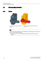
Page 84: ...ism 8 3 1 Versions Direct operating mechanism standard ver sion gray Direct operating mechanism standard version red yellow Note Handles in the colors red yellow are used for Emergency Off applications and the handles in gray are used for all other applications The standard version of the direct operating mechanism can be locked with up to 3 padlocks ...

Page 85: ...m 1 2 3 4 6 4 5 4 8 8 4 8UD door coupling rotary operating mechanism The door coupling rotary operating mechanism can be used to operate the switch disconnector from outside the cabinet door Note Door coupling rotary operating mechanism can only be mounted on a 3KF without direct operating mechanism installed in the factory Mounting on 3KF switch disconnectors with a direct operating mechanism ins...

Page 86: ...ses 84 Manual 09 2019 L1V30580914002A 01 8UD series Modern design of the handles identical with the handles which are used on the new range of 3VA MCCBs Locking function on the handle with padlocks Optional illumination of switching symbols on the handle Test function of auxiliary switches is supported ...

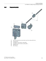
Page 87: ...ctors with fuses Manual 09 2019 L1V30580914002A 01 85 8 4 1 Component overview Handle including front cover seal and screws for mounting on front door Inscription label Coupling driver with tolerance compensation Coupling driver without tolerance compensation Extension shaft Shaft coupling ...

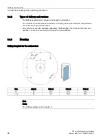
Page 88: ... includes a handle without illumination a coupling driver with tolerance compensation and a 300 mm long extension shaft All components are also available separately Shaft lengths of 300 mm and 600 mm and handles in versions with and without illumination are available 8 4 3 Mounting Drilling template for the cabinet door Size A mm B mm C mm D mm 1 2 65 10 5 Ø 30 Ø 4 5 3 4 5 88 13 5 Ø 65 Ø 5 5 Note ...

Page 89: ... 3KF switch disconnector in the cabinet in the dimensional drawings of the 3KF See chapter Drilling templates Page 116 The clearance between the center hole in the cabinet door shaft and the hinge of the cabinet door must be at least 80 mm Note Hinge clearance The smaller the hinge clearance compared with the total width of the cabinet door the smaller the force required to prevent unintended open...

Page 90: ...he locking function in the ON position Mounting of the inscription label If you want to use these functions accessories you should perform the necessary steps before continuing to mount the handle on the door You will find more information on the functions accessories in chapters Functions and operation Page 94 and Accessories for 8UD Page 103 Size 1 2 PZ2 1 1 1 3 Nm 3 4 5 2 1 2 4 Nm Note 8UD hand...

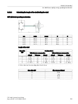
Page 91: ... 3KF3 355 5 422 0 129 8 43 3KF4 320 0 391 0 110 0 43 3KF5 307 0 405 5 152 5 43 Length of the shaft Size of the 3KF Coupling drivers With tolerance compensation Without tolerance compensation A mm Tolerance B mm A mm Tolerance B mm 1 2 X 96 5 X 111 X 54 5 X 69 3 X 99 5 10 X 136 5 X 57 5 10 X 94 5 4 X 10³ 10 X 153 X 61 10 X 111 5 X 117 5 10 X 195 5 X 75 5 10 X 153 5 X Min clearance from mounting pla...

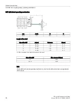
Page 92: ...g mechanism mm A min E C 3KF3 61 0 22 5 1 0 Length of the shaft Size of the 3KF A mm Tolerance B mm 1 2 X 14 5 X 1 3 X 20 10 X 1 4 X 34 10 X 1 5 X 53 10 X 1 X Min clearance from switch to outside of side wall Size of the 3KF Min clearance X mm 1 2 28 5 3 4 5 33 5 Note On the 3KF with lateral operating mechanism only drivers without tolerance compensation can be used ...

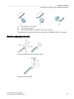
Page 93: ...A 01 91 Mark dimension B on the shaft Saw the shaft to length A Deburr the cutting edges of the shaft to enable proper mounting The dimensions for A and B can be found in the section Cutting the shaft in this chapter Attach the coupling driver to the shaft Push the shaft into the driver as far as it will go Fasten the shaft to the 3KF ...

Page 94: ...ating mechanism 3KF switch disconnectors with fuses 92 Manual 09 2019 L1V30580914002A 01 Push the shaft into the 3KF as far as marking B Sizes 1 to 5 Size 1 1 5 mm 0 8 1 0 Nm 2 2 0 mm 1 5 2 0 Nm 3 2 5 mm 4 0 4 5 Nm 4 3 0 mm 7 0 7 5 Nm 5 2 5 mm 4 0 4 5 Nm ...

Page 95: ... point on the 3KF as well as by tolerances between the 3KF and the mounting plate or standard mounting rail in the cabinet In the usual applications the taper on the rear plate of the handle ensures that the coupling head engages in the handle even in the event of deflection If the 3KF is mounted on standard mounting rails and shafts that are longer than 300 mm the deflection of the coupling head ...

Page 96: ... can be closed Coupling head deflected strongly downwards cabinet door cannot be closed Coupling head deflected strongly downwards 8UD handle with shaft jack 8UD1900 0FA00 cabinet door can be closed 8 4 4 Functions and operation 8 4 4 1 Door interlocking The door interlock of the door coupling rotary operating mechanism locks the door as soon as the door coupling rotary operating mechanism is turn...

Page 97: ...cking Door interlocking can be overridden by a deliberate action This means that the door can also be opened with the operating mechanism in the ON position I e g for maintenance purposes 1 Press in the door interlocking pin using a pointed object 2 Keep the pin pressed while opening the door NOTICE Material damage Risk of damage to the device When overriding door interlocking ensure that the 8UD ...

Page 98: ...e lever on the rear of the front cover of the 8UD must be turned to the vertical position using a slotted screwdriver 2 5 mm Activated door interlocking Deactivated door interlocking Note The lever for deactivation of the door interlock is only accessible as long as the handle has not yet been mounted on the cabinet door If you want to deactivate door interlocking ensure that the lever is in the c...

Page 99: ...le and the 3KF switch disconnector are in the same position both ON or OFF before you close the cabinet door Otherwise the operating mechanism can be damaged Tolerance compensation The door coupling rotary operating mechanism is supplied with tolerance compensation as standard This device compensates potential minor offsets between the rotary switch of the cabinet door and the shaft of the door co...

Page 100: ...cabinet door cannot be opened Door interlocking cannot be overridden The rotary operating mechanisms can be locked with up to three padlocks with a shackle diameter of 4 5 to 9 5 mm The padlocks are not included in the scope of supply 8 4 4 5 Enabling interlocking in the ON position 8UD handles can be modified in a way to allow interlocking in the OFF and ON position Note This modification is not ...

Page 101: ...operating lever on the front cover again Test interlocking in the ON position before installation in the cabinet door The rotary operating mechanisms can be locked with up to three padlocks with a shackle diameter of 4 5 to 9 5 mm Note The 3KF can also be used as an Emergency Off switch with handle in red yellow In this case the interlocking function is not permissible in the ON position ...

Page 102: ...ore details on the test function in chapter Auxiliary switches Page 63 Switching to the test position The test position is located 20 counterclockwise from the OFF position and is mechanically blocked to prevent accidental switching to this position when switching normally from ON to OFF Procedure 1 Press in the test position pin using a pointed object with a diameter of 2 mm or less 2 Keep the pi...

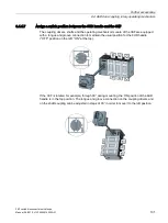
Page 103: ...operating mechanism module of the 3KF are equipped with a tongue and groove connection to maintain the usual position for the 8UD handle OFF position on the left ON at the top If the 3KF is rotated for example through 90 during mounting the ON position of the 8UD handle is in the top position The tongue and groove connection on the coupling drivers and on the shaft coupling can be adjusted in step...

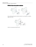
Page 104: ...ch disconnectors with fuses 102 Manual 09 2019 L1V30580914002A 01 Modification of tongue and groove joint on coupling driver Remove the tongue and groove connection using a tool e g a screwdriver by pressing against it from inside Mount it in the required position again outside ...

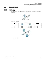
Page 105: ...uses Manual 09 2019 L1V30580914002A 01 103 8 4 5 Accessories for 8UD 8 4 5 1 Shaft coupling The shaft coupling is used if the shaft length of 300 600 mm is not sufficient and needs to be extended For sizes 1 to 4 of the 3KF Size A mm 1 2 8 mm 2 6 3 0 Nm 28 3 4 8 mm 5 4 6 0 Nm 40 For size 5 of the 3KF ...

Page 106: ...2 Shaft jack for sizes 1 and 2 The shaft jack can be used if the coupling head is too widely deflected and the cabinet door cannot be closed due to a mechanical collision between the coupling head and the 8UD handle The accessory part is required for standard rail mounting and use of shafts longer than 300 mm Size 1 2 PZ2 1 1 1 3 Nm 3 4 5 2 1 2 4 Nm ...

Page 107: ...9 2019 L1V30580914002A 01 105 8 4 5 3 Inscription label The labeling plate can be used for inscription directly on the front of the 8UD handle The inscription area is 44 5 x 14 5 mm Mounting Remove the knockout on the rear panel of the front cover of the 8UD Snap the labeling plate onto the front cover of the 8UD ...

Page 108: ...Further accessories 8 4 8UD door coupling rotary operating mechanism 3KF switch disconnectors with fuses 106 Manual 09 2019 L1V30580914002A 01 ...

Page 109: ...3KF switch disconnectors with fuses Manual 09 2019 L1V30580914002A 01 107 Maintenance 9 No maintenance procedures are necessary ...

Page 110: ...Maintenance 3KF switch disconnectors with fuses 108 Manual 09 2019 L1V30580914002A 01 ...

Page 111: ... 220 Rated insulation voltage Ui V 1000 Rated impulse withstand voltage Uimp kV 12 Overvoltage category IV Operating and short circuit behavior Rated operational current Ie 2 At AC 21A AC 22A AC 23A 400 690 V A 32 63 80 125 160 250 400 630 800 At DC 21A DC 22A DC 23A 220 440 V A 32 63 80 125 160 250 400 630 800 Motor switching capacity AC 23A3 At 400 V kW 15 30 37 55 90 132 220 355 400 At 500 V kW...

Page 112: ...50 2600 10400 7000 Power loss per pole of the switch at Ith plus fuses W 0 4 1 7 208 4 2 7 2 15 26 40 50 Maximum power loss of the usable fuses per fuse For 3KF LV HRC For 3KF SITOR W W 6 5 7 7 5 8 8 5 12 11 20 12 26 25 5 36 34 55 48 68 60 85 Service life operating cycles Mechanical Electrical at AC 23A 690 V 50 60 Hz Electrical at AC 23A 440 V 50 60 Hz Electrical at DC 23A 440 V 15000 6000 10000 ...

Page 113: ...ded as a guide only and may vary depending on the make of motor 4 Valid for combination of 3KF and fuse type 3NA 3ND characteristic gG aM 10 1 Technical specifications accessories Additional poles The technical specifications of the additional poles 4th contact element N terminal and N PE terminal correspond to those of the 3KF main switch See chapter 3 and 4 pole versions of the 3KF switch discon...

Page 114: ...t mA 1 Degree of protection acc to IEC 60529 Terminals IP20 Contact compartment IP40 Ambient conditions Ambient temperature During operation C 25 70 During storage C 40 80 Degree of pollution 3 Endurance Mechanical 10 million Electrical 10 million At AC 15 with 3RT1015 to 3RT1026 contactors 10 million At DC 12 DC 13 The electrical endurance with DC depends not only on current but also on voltage l...

Page 115: ...nnectors with fuses Manual 09 2019 L1V30580914002A 01 113 Operating behavior Rated operational current Ie At AC 12 A 10 At AC 15 Up to 230 V A 8 At 400 V A 8 At DC 12 At 24 V A 10 At 48 V A 5 At 110 V A 2 5 At 230 V A 1 At DC 13 At 24 V A 3 At 48 V A 1 5 At 110 V A 0 7 At 230 V A 0 3 ...

Page 116: ...Technical specifications 10 1 Technical specifications accessories 3KF switch disconnectors with fuses 114 Manual 09 2019 L1V30580914002A 01 ...

Page 117: ...minals 10 0 0 10 3 Flat terminals 10 0 0 10 4 Flat terminals 10 0 0 10 5 Flat terminals 10 0 0 10 6 Flat terminals 10 0 0 10 3KF SITOR Size Terminal A mm B mm C mm D mm 1 Box terminals 10 20 20 10 2 Flat terminals 10 30 30 10 3 Flat terminals 10 30 30 10 4 Flat terminals 10 30 30 10 5 Flat terminals 10 30 30 10 6 Flat terminals 10 30 30 10 Note The dimensions A and D can be reduced to 0 mm if phas...

Page 118: ...used Use phase barriers or cable connection covers if applicable according to chapter Phase barriers Page 52 3KF LV HRC Size Terminal A mm B mm 1 Box terminals 0 2 Flat terminals 0 8 3 4 5 Flat terminals 0 14 3KF SITOR Size Terminal A mm 1 Box terminals 20 2 Flat terminals 20 3 4 5 Flat terminals 20 11 2 Drilling templates This chapter describes the drilling templates for floor mounting and door c...

Page 119: ...Size 1 Article num ber Size Poles Terminal A mm B mm C mm D mm E mm F mm G mm 3KF1303 0LB11 1 3 Box terminals 112 56 57 27 4 5 99 5 20 5 3KF1303 0MB11 1 3 Box terminals 112 56 20 5 27 4 5 103 19 5 3KF1303 0MR11 1 3 Flat terminals at the rear 70 35 69 5 197 5 4 5 197 5 69 5 3KF1403 0LB11 1 4 Box terminals 112 56 57 27 4 5 136 20 5 3KF1403 0MB11 1 4 Box terminals 112 56 20 5 27 4 5 129 5 46 ...

Page 120: ...87 220 4 5 220 3KF2412 0LF11 2 4 Flat terminals 110 52 18 5 219 4 2 219 3KF2412 0MF11 2 4 Flat terminals 110 52 109 5 219 4 2 219 3KF3325 0LF11 3 3 Flat terminals 161 75 5 24 225 6 6 225 3KF3325 0MF11 3 3 Flat terminals 161 75 5 83 225 6 6 225 3KF3425 0LF11 3 4 Flat terminals 161 75 5 24 284 6 6 284 3KF3425 0MF11 3 4 Flat terminals 161 75 5 142 284 6 6 284 3KF4340 0LF11 4 3 Flat terminals 161 75 5...

Page 121: ...914002A 01 119 Size 5 Article number Size Poles Terminal A mm B mm C mm D mm E mm F mm G mm 3KF5363 0LF11 5 3 Flat termi nals 210 95 35 361 8 4 361 10 3KF5363 0MF11 5 3 Flat termi nals 210 95 132 361 8 4 361 10 3KF5463 0LF11 5 4 Flat termi nals 210 95 35 458 8 4 458 10 3KF5463 0MF11 5 4 Flat termi nals 210 95 229 458 8 4 458 10 ...

Page 122: ... L1V30580914002A 01 11 2 1 Drilling templates for 8UD door coupling rotary operating mechanisms mm A B C D 8UD1131 65 10 5 30 4 5 8UD1731 8UD1141 88 13 5 65 5 5 8UD1151 8UD1161 8UD1841 8UD1851 8UD1861 Note 8UD with illumination The lock hasp diameter of 3 mm is only required when the illuminated version of the 8UD is used ...

Page 123: ...ensional drawings 3KF switch disconnectors with fuses Manual 09 2019 L1V30580914002A 01 121 11 3 Dimensional drawings 11 3 1 Basic units The following dimensions are measured in mm Size 1 of the 3KF front operating mechanism with box terminals 3KF LV HRC ...

Page 124: ...ling templates 11 3 Dimensional drawings 3KF switch disconnectors with fuses 122 Manual 09 2019 L1V30580914002A 01 3KF SITOR Note Additional dimensions for complete units with direct handle please see accessories for direct handle ...

Page 125: ...123 3KF sizes 2 to 5 3KF LV HRC Size A B C D E F G H I J K L M N O P Q R 2 20 46 44 9 47 139 219 274 306 150 110 65 42 161 5 32 25 45 93 5 7 3 25 59 60 7 5 67 5 184 284 355 337 207 161 93 49 188 37 45 45 129 8 10 4 30 72 60 13 67 5 184 336 420 387 215 161 93 46 5 205 77 45 45 110 10 5 50 97 90 15 80 219 458 569 270 210 64 264 45 45 152 5 11 ...

Page 126: ...2A 01 Size A B C D E F G H I J K L M N O P Q S 2 20 46 204 2 173 15 5 83 5 206 130 65 150 110 100 139 130 32 25 45 39 5 42 3 25 59 257 8 225 17 107 5 278 182 93 207 161 145 184 176 45 45 61 5 49 4 30 72 304 1 214 21 118 315 190 93 215 161 145 184 223 9 45 15 45 43 46 5 5 50 97 413 4 361 23 5 113 5 234 270 210 180 219 263 9 77 5 45 60 5 64 ...

Page 127: ...3 187 6 70 4 7 46 46 53 44 9 20 173 3KF3 248 9 244 91 6 6 60 5 59 77 5 60 11 25 225 3KF4 288 6 283 5 104 6 6 66 72 77 5 60 11 30 264 3KF5 393 9 388 145 8 4 93 5 97 100 90 14 50 361 mm M N O P Q R S T X Y Z 3KF2 206 65 110 150 11 5 36 2 5 104 99 155 118 3KF3 278 93 161 207 8 41 3 145 129 8 178 5 172 3KF4 315 93 161 215 8 5 38 4 145 110 190 5 193 3KF5 210 270 13 5 50 5 6 180 152 5 240 231 ...

Page 128: ...sizes 1 and 2 with flat terminals Optional mounting position Illustration of 3KD is comparable with 3KF Size A mm Box terminals 1 18 Flat terminals 2 27 3 44 4 60 5 90 3KF Size Width of 4th pole Width of neutral conductor terminal Width N PE terminal 1 38 4 18 18 2 48 44 44 3 61 60 60 4 74 60 60 5 100 90 90 Note The 4th pole can only be mounted on a 3 pole 3KF For further dimensions side view and ...

Page 129: ...anual 09 2019 L1V30580914002A 01 127 11 3 3 Auxiliary switch module Auxiliary switch module for size 1 Note The auxiliary switch modules with test function can only be mounted directly next to the operating mechanism module of the 3KF switch disconnector 11 3 4 Phase barriers Phase barriers for sizes 2 to 5 ...

Page 130: ...ng templates 11 3 Dimensional drawings 3KF switch disconnectors with fuses 128 Manual 09 2019 L1V30580914002A 01 Phase barriers for sizes 3 and 4 Size A mm B mm C mm D mm 3 313 253 106 5 68 4 389 317 122 75 Phase barriers for size 5 ...

Page 131: ...n cover Cable connection covers for sizes 2 to 5 Size Version A mm B mm C mm 2 Standard 240 78 52 Short 194 55 52 3 Standard 317 108 5 81 Short 218 59 81 4 Standard 401 128 93 5 Short 280 67 5 93 5 5 Standard 450 135 117 5 Note Cable connection covers can be mounted on the operating mechanism module of the 3KF switch disconnector to cover mounted auxiliary switches ...

Page 132: ...F switch disconnectors with fuses 130 Manual 09 2019 L1V30580914002A 01 11 3 6 Direct operating mechanism Direct handle for size 1 Note Can be locked with 3 padlocks requires additional mounting depth in the locked state For dimensions of the rotary axis see the basic unit ...

Page 133: ...ional drawings 3KF switch disconnectors with fuses Manual 09 2019 L1V30580914002A 01 131 Direct handle for size 2 Note Can be locked with 3 padlocks requires additional mounting depth in the locked state For dimensions of the rotary axis see the basic unit ...

Page 134: ...ional drawings 3KF switch disconnectors with fuses 132 Manual 09 2019 L1V30580914002A 01 Direct handle for size 3 Note Can be locked with 3 padlocks requires additional mounting depth in the locked state For dimensions of the rotary axis see the basic unit ...

Page 135: ...ional drawings 3KF switch disconnectors with fuses Manual 09 2019 L1V30580914002A 01 133 Direct handle for size 4 Note Can be locked with 3 padlocks requires additional mounting depth in the locked state For dimensions of the rotary axis see the basic unit ...

Page 136: ...ional drawings 3KF switch disconnectors with fuses 134 Manual 09 2019 L1V30580914002A 01 Direct handle for size 5 Note Can be locked with 3 padlocks requires additional mounting depth in the locked state For dimensions of the rotary axis see the basic unit ...

Page 137: ... L1V30580914002A 01 135 11 3 7 8UD door coupling rotary operating mechanism Handle of 8UD door coupling rotary operating mechanism for size 1 Handle of 8UD door coupling rotary operating mechanism for size 2 Handle of 8UD door coupling rotary operating mechanism for sizes 3 to 5 Size A mm B mm 3 106 13 4 140 13 5 200 15 ...

Page 138: ...Dimensional drawings and drilling templates 11 3 Dimensional drawings 3KF switch disconnectors with fuses 136 Manual 09 2019 L1V30580914002A 01 ...

Page 139: ... voltage switchgear and controlgear Standardized mounting on rails for mechanical support of electrical devices in switchgear and controlgear installations DIN 46234 Cable lugs for solderless connections ring type without insulating sleeve for copper conductors DIN 46235 Cable lugs for compression connections cover plate type for copper conductors DIN 46206 2 Connections for electrical equipment f...

Page 140: ...or the 3KF switch disconnector online in the Siemens Industrial Online Support https support industry siemens com cs ww en ps cert Environmental compatibility All materials used are environmentally sustainable in compliance with the Siemens standard 36 350 Hazardous substances list of prohibited substances list of substances to be avoided You will find further technical documentation online https ...

Page 141: ... immediately before touching an electronic module To do this touch a conductive grounded object e g a bare metal part of a switch cabinet or the water pipe Always hold the component by the plastic enclosure Electronic modules should not be brought into contact with electrically insulating materials such as plastic film plastic parts insulating table supports or clothing made of synthetic fibers Al...

Page 142: ...witch disconnectors with fuses 140 Manual 09 2019 L1V30580914002A 01 1 ESD seat 2 ESD standing position 3 ESD seat and ESD standing position Protective measures a Conductive floor b ESD table c ESD footwear d ESD smock e ESD bracelet f Cubicle ground connection ...

Page 143: ...ctrical Manufacturers Association NFPA National Fire Protection Association NO Normally open contact LV Low voltage LV fuse Low voltage fuse R RESET RMS Root mean square T Test UL Underwriters Laboratories Inc VDE Verband der Elektrotechnik Elektronik und Informationstechnik Association for Electrical Electronic and Information Technologies VDI Verein Deutscher Ingenieure Association of German Eng...

Page 144: ...t Ic Let through current Ik Short circuit current IKD Uninterrupted short circuit current IK MAX Maximum short circuit current Ie Rated operational current IP Rated peak withstand current impulse short circuit current Isc Prospective current Ith Conventional free air thermal current IU Rated uninterrupted current U Voltage across main contacts Ue Maximum voltage rated operating voltage ...

Page 145: ...tric conductor cross sections according to VDE Verband der Elektrotechnik Elektronik und Informationstechnik mm2 Conductor cross sections according to AWG American Wire Gauge or kcmil thousand circular mils Conversion table AWG mm2 AWG kcmil Diameter d mm mm2 Metric equivalent mm2 AWG 20 0 81 1 0 52 0 75 18 1 02 1 0 82 1 16 1 29 1 1 3 1 5 14 1 63 1 2 08 2 5 12 2 05 1 3 31 4 10 2 59 1 5 26 6 8 3 26...

Page 146: ...ly stranded conductors for classes B C and D Source Standard UL 83 Other conversions Conversion factors for units of length Length Conversion factor 1 inch 25 4 millimeters mm 1 centimeter 0 3937 inches Conversion factors for units of weight Weight Conversion factor 1 ounce oz 28 35 grams g 1 pound Ib 0 454 kilograms kg 1 kilogram kg 2 205 pounds Ib Conversion factors for units of temperature Temp...

Page 147: ...914002A 01 145 Temperature 25 C 13 F 30 C 22 F Conversion factors for tightening torques Tightening torque Conversion factor 1 Newton meter Nm 8 85 Ib F in 8 85 Ib in inch pound 1 36 Newton meters Nm 1 Ib F ft 1 Ib ft inch pound 0 113 Newton meter Nm 1 Ib F in 1 Ib in inch pound ...

Page 148: ...Conversion tables 3KF switch disconnectors with fuses 146 Manual 09 2019 L1V30580914002A 01 ...

Page 149: ...e Limited short circuit currents occur if the switching device reduces the amplitude of the short circuit current due to for example resistance switching delay or peak arc voltage The let through current of a device such as a current limiting fuse or a current limiting molded case circuit breaker determines the thermal load I2t value imposed on equipment connected downstream of the device current ...

Page 150: ...ty Ics is the short circuit current determined by the switching voltage that a switch disconnector is capable of interrupting repeatedly test sequence 0 C0 CO formerly P 2 After a load break switch has interrupted a short circuit it can continue to carry the rated operational current despite increased self heating Rated short circuit breaking capacity The rated short circuit breaking capacity Icn ...

Page 151: ...brief load conditions Calculation of the rated short time withstand current usually refers to a period of 1 s If the reference period differs from that stated above it must be specified The rated short time withstand current is specified for the distribution and or main busbars of a switchgear assembly Rated ultimate short circuit breaking capacity The rated ultimate short circuit breaking capacit...

Page 152: ...haracteristic for the dynamic stress is the rated peak withstand current i e the maximum instantaneous value of the short circuit current The characteristic for the thermal stress of the short circuit current is the root mean square value of the short circuit current throughout its duration Switching capacity The rating is the power that a switching device is capable of switching at the associated...

Page 153: ...1 AC applications 47 Accessories 8UD door coupling rotary operating mechanism 83 Additional poles 20 Cable connection covers 25 Phase barriers 24 Accessories 8UD Inscription label 105 Shaft coupling 103 Shaft jack 104 Activate interlocking function 8UD 98 Additional poles 4th contact element 70 Accessories 20 Auxiliary switch module 70 Mounting 76 N terminal 70 N PE terminal 70 Technical specifica...

Page 154: ...129 Direct operating mechanism 130 Phase barriers 127 Size 1 121 Sizes 2 5 123 Terminals 126 Direct operating mechanism Dimensional drawings 130 Versions 82 Disassembly Front operating mechanism left 45 Front operating mechanism right and center 45 Discharge 139 Door interlocking 8UD 94 Overview 96 Drilling template Size 1 flat terminals at the rear 38 Size 1 SITOR 36 Size 1 LV HRC 39 Size 5 43 Si...

Page 155: ... Main circuit connection 47 Flat terminals 51 Permissible circuits 47 Phase barriers 52 Maintenance 107 Manual operation 31 Minimum clearance Phase barriers 55 Mounting Additional poles 76 Auxiliary switches 66 67 Handle 88 Mounting bracket Floor mounting 40 Mounting position 34 N N terminal Additional poles 70 N PE terminal Additional poles 70 O Overriding door interlocking 8UD 95 Overview Availa...

Page 156: ...n locations 75 Standard rail mounting 16 Front operating mechanism left 45 Front operating mechanism right and center 44 Standards 137 Storage 139 Stripping insulation Box terminals 49 Structure Article numbers 30 Switching instant 68 Auxiliary switches 63 66 Setting 68 Symbols 141 T Technical specifications 109 Additional poles 111 Auxiliary switches 111 Box terminals 50 Temperatures Conversions ...

Page 157: ......

Page 158: ......

Reviews: