Connection and commissioning
5.3 Mounting accessories
3VA27 molded case circuit breakers & 3WL10 air circuit breakers
180
Manual, 10/2018, L1V30499596002-01
3.
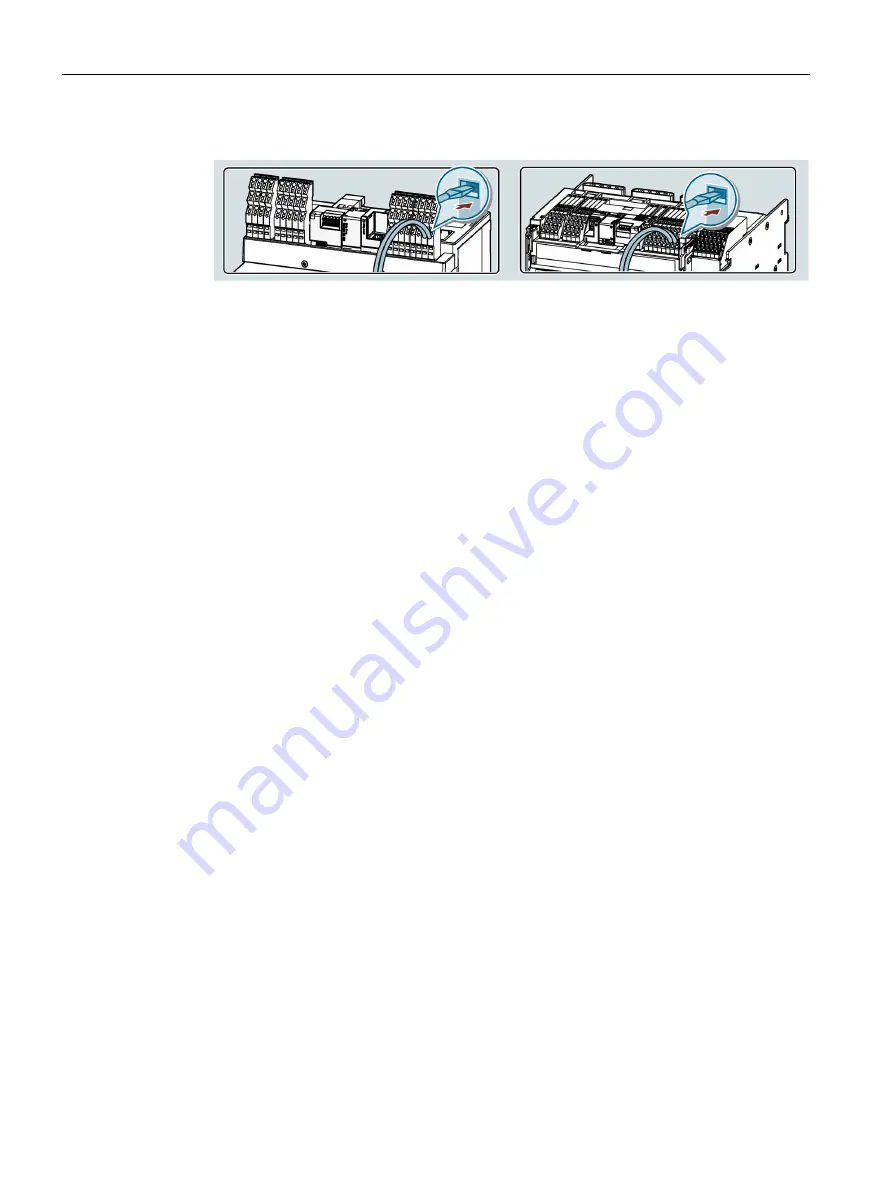
Wire the accessories to the terminals for auxiliary supply connection as required.
All commands and signals for interaction with the circuit breaker pass through the
auxiliary conductor terminal system and the auxiliary conductor terminals it contains or
the CB Bus Module that is plugged in. The internal wiring to the corresponding pins is
available on every circuit breaker. By studying the labeling shown below, the user will find
the relevant pin assignment for the external wiring of the user's accessories to the
corresponding auxiliary conductor terminals. These are implemented with a screwless
push-in method and are pre-installed in the factory when internal accessories are
configured.
For the precise wiring of each accessory item, see the circuit diagrams (see Chapter
Circuit diagrams (Page 245)).


