Connection and commissioning
5.4 Commissioning
Air circuit breaker 3WL10
Manual, 11/2017, L1V30499596002-01
147
5.4.2
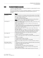
Procedure for testing the accessories
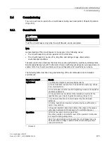
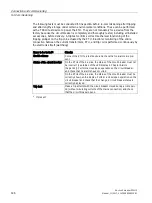
To meet the high quality requirements of Siemens, this points are already tested if the circuit
breaker is configured in the factory.
The accessories therefore only need to be tested after installation or conversion by the user.
The following points must be considered during commissioning after conversion or
installation:
Accessories to be tested
Method
Geared motor
1. Run the geared motor for charging the springs at the appropriate nominal voltage.
Result: The springs are correctly charged. The signals are normal. When the springs
are charged, the geared motor stops.
2. Perform a few close and open operations.
Result: The geared motor charges the springs again after every closing operation.
NOTE: If there is one, switch on the undervoltage coil in advance.
Undervoltage coil
1. Run the undervoltage coil at the appropriate rated voltage and perform the closing
operation on the circuit breaker.
Result: The circuit breaker closes correctly. The behavior and the signals of the
auxiliary switches are normal.
2. Switch off the power supply of the undervoltage release. The circuit breaker opens.
3. Operate the undervoltage coil at the appropriate nominal voltage and perform the
closing operation on the circuit breaker.
Result: The circuit breaker closes. The behavior and the signals of the auxiliary
switches are correct.
Note: If the undervoltage coil is tripped by a shunt release (ST), the circuit breaker
cannot be reclosed until voltage is applied to the undervoltage coil again. Make sure
that the coil was really tripped by a power failure. Otherwise examine the circuit
breaker and the device in question to see whether both are fully functional.
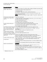
Shunt release (ST)
1. Close the circuit breaker.
2. Operate the opening coil at the appropriate nominal voltage.
Result: The circuit breaker opens correctly. The signals at the auxiliary switches are
correct.
Closing coil (CC)
1. Open the circuit breaker.
2. Charge the springs manually or electrically.
3. Operate the closing coil at the appropriate nominal voltage.
Result: The circuit breaker closes correctly. The signals at the auxiliary switches are
correct.
Shunt release (ST) with
actuator module COM ACT
1. Supply power to the ETU with the auxiliary voltage at the Breaker Connect module.
2. Switch on the contacts of the actuator module.
3. Close the circuit breaker.
4. Choose item "Open CB" in the menu of ETUs of the 6-series.
Result: The circuit breaker opens correctly. The behavior and the signals of the
auxiliary switches are normal.
Note: The test can be conducted if voltage is applied to the ETU and to the coils.
Summary of Contents for SENTRON 3WL10
Page 1: ......
Page 2: ......
Page 8: ...Table of contents Air circuit breaker 3WL10 6 Manual 11 2017 L1V30499596002 01 ...
Page 170: ...Operation 6 3 Troubleshooting Air circuit breaker 3WL10 168 Manual 11 2017 L1V30499596002 01 ...
Page 180: ...Technical specifications Air circuit breaker 3WL10 178 Manual 11 2017 L1V30499596002 01 ...
Page 199: ...Air circuit breaker 3WL10 Manual 11 2017 L1V30499596002 01 197 Circuit diagrams 10 ...
Page 212: ...Circuit diagrams Air circuit breaker 3WL10 210 Manual 11 2017 L1V30499596002 01 ...
Page 233: ......
Page 234: ......


