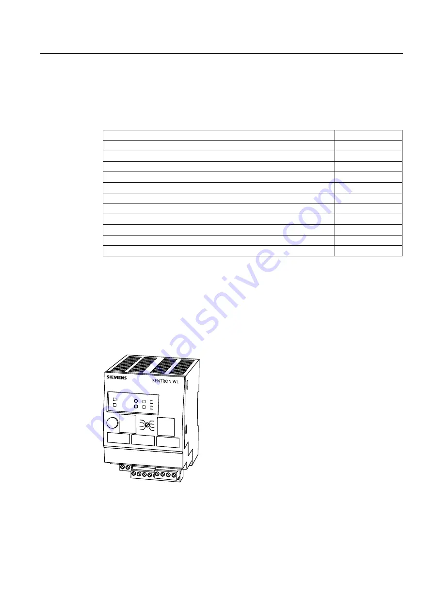
3WL air circuit breakers
3.5 External CubicleBUS modules
3WL/3VL circuit breakers with communication capability - PROFIBUS
System Manual, 03/2011, A5E01051353-02
69
3.5.2.2
Technical data
The table below contains the technical data of the digital input module on the CubicleBUS:
Table 3- 16 Technical data of the digital input module
Operating voltage on the CubicleBUS min./max. (V)
19.2 / 28.8
Current consumption from the CubicleBUS min./max. (mA)
29 / 43
Number of isolated channels per digital input module
6
Voltage value for reliable detection of a "1" signal (V)
> 16 V
Current consumption per input at a "1" signal (mA)
7.5
Voltage value for reliable detection of a "0" signal (V)
< 1 V
Current consumption per input at a "0" signal (mA)
0
Maximum number of modules possible on one CubicleBUS
2
Power loss min./max. (W)
0.72 / 0.94
Dimensions W/H/D (mm)
70 / 86 / 95
Weight (kg)
0.223
Temperature range (°C)
-20 / 60
3.5.3
Digital output module with rotary coding switch
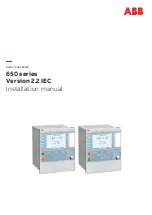
Six binary information items about the switch status (alarms and tripping operations) can be
output via the digital output module to external signaling devices (e.g. indicator lights, horns),
or used for selective shutdown of other plant units (e.g. frequency converters).
The switch position on the left selects the events in the adjacent dark-gray field, and the
switch position on the right selects the events in the adjacent light-gray field.
$/$50
35(75,3
78(55
/'6+('
/'5(67
7(03
,81%$/
Figure 3-18 Digital output module


