Connection
6.2 Connecting the main circuit
Manual, 08/2017, L1V30368969104A-02
67
Connecting versions 7 and 8
Requirements
●
Main circuit is disconnected
●
Transfer switching equipment is in the "Manual" position
●
Copper bar connection kit is mounted
Procedure
The bolt set required for mounting is not included with the transfer switch. You can find the
bolt set requirements in the following table:
Version
Bolt
Washer
Nut
7 (horizontal)
2000 … 2500 A
10 x H M12-55 6.8
20 x
10 x
8 (horizontal)
3200 A
10 x H M12-65 6.8
20 x
10 x
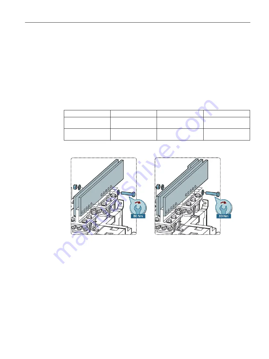
1.
Mount the busbar with 10 bolts, 20 washers and 10 nuts on the transfer switching
equipment.
Figure 6-42 Connecting versions 7 and 8
2.
Connect the mounted transfer switching equipment to the power supply systems.
–
For the 3-pole type with 3 x the above listed bolt set.
–
For the 4-pole type with 4 x the above listed bolt set.
Summary of Contents for SENTRON
Page 1: ......
Page 2: ......
Page 10: ...Introduction 10 Manual 08 2017 L1V30368969104A 02 ...
Page 12: ...General information 2 1 Certification 12 Manual 08 2017 L1V30368969104A 02 ...
Page 24: ...Product information 3 2 Product family 24 Manual 08 2017 L1V30368969104A 02 ...
Page 26: ...Functions 26 Manual 08 2017 L1V30368969104A 02 ...
Page 176: ...Accessories 9 18 Electronic module 3KC8 only 176 Manual 08 2017 L1V30368969104A 02 ...
Page 220: ...Appendix A 3 Storage conditions 220 Manual 08 2017 L1V30368969104A 02 ...


