Operation
7.2 Functions of the inputs and outputs
Manual, 08/2017, L1V30368969104A-02
123
7.2.3.5
Outputs of the electronic module
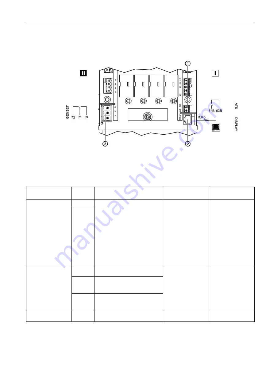
The following outputs are located on the electronic module:
①
Output – relay of the operational readiness of the device
②
Output – 3KC9823-0 display (optional)
③
Output – switching the generator on/off
Figure 7-13 Outputs of the electronic module
Designation
Pin
Explanation
Properties
Recommended
cable cross-section
Relay of operational
readiness
63B
Availability of the electronic module
and of the motor operator:
•
Open if the electronic module
and/or motor operator of the
transfer switching equipment
are not available.
•
Closed if the switch on the
motor operator is at the "Auto"
position and the electronic
module and the motor operator
are ready for operation.
Floating contacts 2 A
AC1 / 250 V
1.5 - 2.5 mm
2
64B
Switching the genera-
tor on/off
71
Common control terminal for pins
72 and 74
Floating contacts 2 A
AC1 / 250 V
1.5 - 2.5 mm
2
72
Signal for starting / stopping the
generator: NC contact (normally
closed contact)
74
Signal for starting / stopping the
generator: NO contact (normally
open contact)
Display connection
To display Output for the optional 3KC9823-0
display
Cable length up to 3 m RJ45
Summary of Contents for SENTRON
Page 1: ......
Page 2: ......
Page 10: ...Introduction 10 Manual 08 2017 L1V30368969104A 02 ...
Page 12: ...General information 2 1 Certification 12 Manual 08 2017 L1V30368969104A 02 ...
Page 24: ...Product information 3 2 Product family 24 Manual 08 2017 L1V30368969104A 02 ...
Page 26: ...Functions 26 Manual 08 2017 L1V30368969104A 02 ...
Page 176: ...Accessories 9 18 Electronic module 3KC8 only 176 Manual 08 2017 L1V30368969104A 02 ...
Page 220: ...Appendix A 3 Storage conditions 220 Manual 08 2017 L1V30368969104A 02 ...


