17
Interrupter/Operator Description
Spring Charging Motor
Figure 19a shows the spring charging motor mounted at
the bottom of the left side of the circuit breaker housing. A
mounting bracket holds the motor firmly in place. A
universal motor is used to permit operation on either AC or
DC control power.
The motor control circuits call for automatic charging of
the springs by the motor whenever control power is avail-
able and the springs are discharged. The springs
automatically recharge following a closing operation.
Electrical connections to the motor utilize quick disconnect
terminations for easy inspection or removal.
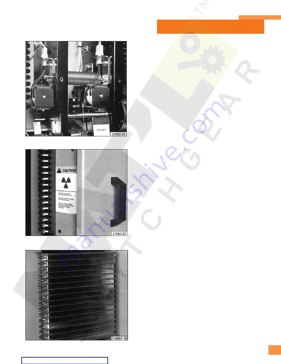
Close Solenoid, Trip Solenoid and Anti-Pump Relay
Figure 2
1 shows the two solenoids controlling operation
of the circuit breaker by external electrical signals.
When the close solenoid is energized it causes the two
closing springs to be released from their extended or
charged state. This forces the three insulating push rods to
move the movable vacuum interrupter contacts vertically
upwards, and close the circuit breaker.
The anti-pump relay
(Figure 41)
electrically isolates signals
to the close solenoid such that only one releasing action
Damper (used with type VS-15050 vacuum interrupters)
(refer to Figures 19a and 37a)
The cylindrical body of the damper has outer threads, for
mating with a threaded adapter which is mounted in the
upper portion of the circuit breaker frame. The body of the
damper is inserted into a cylinder which extends from the
damper down to the connection on the circuit breaker jack
shaft in the lower portion of the operating mechanism.
The damper’s piston head is installed inside the outer
cylinder, which serves to guide the cylinder during
opening and closing operations. The end of the outer
cylinder is attached to triangular damping arms attached
to the circuit breaker jack shaft.
The outer cylinder and (inner) damper remain uncoupled
until the end of the opening operation is reached. At this
time, the cylinder’s striker pin contacts the damper piston,
to begin control of the movable contact dynamics.
Manual Spring Charging
Manual charging of the closing springs is accomplished
using a lever in lieu of the spring charging motor.
Figure
20
shows the principal components of the manual spring
charging mechanism.
The manual spring charging lever is inserted into a rectan-
gular socket in the hand operator. This socket is accessible
through the front panel of the circuit breaker. Moving the
lever up and down in a cranking or pumping motion
causes rotation of the internal spring charging
components.
Figure 21:
Close (Right) and Trip (Left) Solenoids.
Figure 23:
Secondary Disconnect Inside Switchgear.
Figure 22:
Secondary Disconnects on Circuit Breaker.


